Philips Semiconductors
Preliminary data
Low power, low price, low pin count (20 pin)
microcontroller with 4 kbyte OTP
87LPC764
Low Voltage EPROM Operation
The EPROM array contains some analog circuits that are not
save external components and to be able to use pin P1.5 as a
general-purpose input pin.
required when V is less than 4 V, but are required for a V
DD
DD
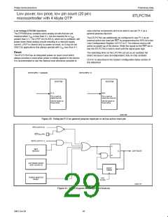
The 87LPC764 can additionally be configured to use P1.5 as an
external active-low reset pin RST by programming the RPD bit in the
User Configuration Register UCFG1 to 0. The internal reset is still
active on power-up of the device. While the signal on the RST pin is
low, the 87LPC764 is held in reset until the signal goes high.
greater than 4 V. The LPEP bit (AUXR.4), when set by software, will
power down these analog circuits resulting in a reduced supply
current. LPEP is cleared only by power-on reset, so it may be set
ONLY for applications that always operate with V less than 4 V.
DD
Reset
The watchdog timer on the LPC764 can act as an oscillator fail
detect because it uses an independent, fully on-chip oscillator.
The 87LPC764 has an integrated power-on reset circuit which
always provides a reset when power is initially applied to the device.
It is recommended to use the internal reset whenever possible to
UCFG1 is described in the System Configuration Bytes section of
this datasheet.
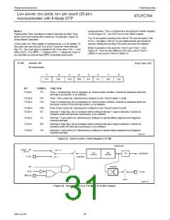
UCFG1.RPD = 1 (default)
UCFG1.RPD = 0
87LPC764
87LPC764
P1.5
RST
Pin is used as
digital input pin
Pin is used as
active-low reset pin
Internal power-on
Reset active
Internal power-on
Reset active
SU01169
Figure 20. Using pin P1.5 as general purpose input pin or as low-active reset pin
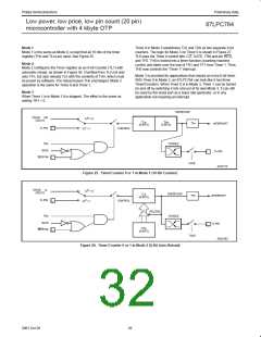
RPD (UCFG1.6)
RST/V PIN
PP
WDTE (UCFG1.7)
S
R
WDT
MODULE
Q
CHIP RESET
SOFTWARE RESET
SRST (AUXR1.3)
RESET
TIMING
POWER MONITOR
RESET
CPU
CLOCK
SU01170
Figure 21. Block Diagram Showing Reset Sources
26
2001 Oct 26

 NXP [ NXP ]