Philips Semiconductors
Preliminary data
Low power, low price, low pin count (20 pin)
microcontroller with 4 kbyte OTP
87LPC764
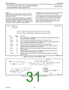
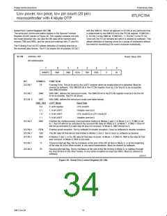
Mode 1
Timer 0 in Mode 3 establishes TL0 and TH0 as two separate 8-bit
counters. The logic for Mode 3 on Timer 0 is shown in Figure 27.
TL0 uses the Timer 0 control bits: C/T, GATE, TR0 and pin INT0,
and TF0. TH0 is locked into a timer function (counting machine
cycles) and takes over the use of TR1 and TF1 from Timer 1. Thus,
TH0 now controls the “Timer 1” interrupt.
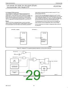
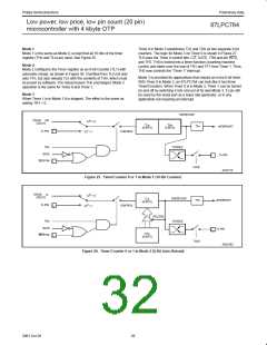
Mode 1 is the same as Mode 0, except that all 16 bits of the timer
register (THn and TLn) are used. See Figure 25
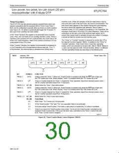
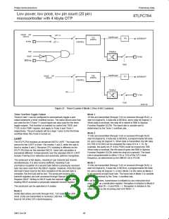
Mode 2
Mode 2 configures the Timer register as an 8-bit Counter (TL1) with
automatic reload, as shown in Figure 26. Overflow from TLn not only
sets TFn, but also reloads TLn with the contents of THn, which must
be preset by software. The reload leaves THn unchanged. Mode 2
operation is the same for Timer 0 and Timer 1.
Mode 3 is provided for applications that require an extra 8-bit timer.
With Timer 0 in Mode 3, an 87LPC764 can look like it has three
Timer/Counters. When Timer 0 is in Mode 3, Timer 1 can be turned
on and off by switching it into and out of its own Mode 3. It can still
be used by the serial port as a baud rate generator, or in any
application not requiring an interrupt.
Mode 3
When Timer 1 is in Mode 3 it is stopped. The effect is the same as
setting TR1 = 0.
OVERFLOW
OSC/6
OSC/12
OR
C/T = 0
TLn
(8 BITS)
THn
(8 BITS)
TFn
INTERRUPT
Tn PIN
CONTROL
C/T = 1
TRn
TOGGLE
GATE
Tn PIN
INTn PIN
TnOE
SU01174
Figure 25. Timer/Counter 0 or 1 in Mode 1 (16-Bit Counter)
OSC/6
OSC/12
or
C/T = 0
OVERFLOW
TLn
TFn
INTERRUPT
(8 BITS)
Tn PIN
CONTROL
C/T = 1
RELOAD
TRn
TOGGLE
GATE
Tn PIN
THn
(8 BITS)
INTn PIN
TnOE
SU01392
Figure 26. Timer/Counter 0 or 1 in Mode 2 (8-Bit Auto-Reload)
29
2001 Oct 26

 NXP [ NXP ]