Philips Semiconductors
Preliminary data
Low power, low price, low pin count (20 pin)
microcontroller with 4 kbyte OTP
87LPC764
For correct activation of Brownout Detect, the V fall time must be
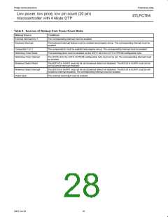
The processor can be made to exit Power Down mode via Reset or
one of the interrupt sources shown in Table 5. This will occur if the
interrupt is enabled and its priority is higher than any interrupt
currently in progress.
DD
no faster than 50 mV/µs. When V is restored, is should not rise
DD
faster than 2 mV/µs in order to insure a proper reset.
The brownout voltage (2.5 V or 3.8 V) is selected via the BOV bit in
the EPROM configuration register UCFG1. When unprogrammed
(BOV = 1), the brownout detect voltage is 2.5 V. When programmed
(BOV = 0), the brownout detect voltage is 3.8 V.
In Power Down mode, the power supply voltage may be reduced to
the RAM keep-alive voltage V
. This retains the RAM contents
RAM
at the point where Power Down mode was entered. SFR contents
are not guaranteed after V has been lowered to V , therefore
DD
RAM
If the Brownout Detect function is not required in an application, it
may be disabled, thus saving power. Brownout Detect is disabled by
setting the control bit BOD in the AUXR1 register (AUXR1.6).
it is recommended to wake up the processor via Reset in this case.
must be raised to within the operating range before the Power
V
DD
Down mode is exited. Since the watchdog timer has a separate
oscillator, it may reset the processor upon overflow if it is running
during Power Down.
Power On Detection
The Power On Detect has a function similar to the Brownout Detect,
but is designed to work as power comes up initially, before the
power supply voltage reaches a level where Brownout Detect can
work. When this feature is activated, the POF flag in the PCON
register is set to indicate an initial power up condition. The POF flag
will remain set until cleared by software.
Note that if the Brownout Detect reset is enabled, the processor will
be put into reset as soon as V drops below the brownout voltage.
DD
If Brownout Detect is configured as an interrupt and is enabled, it will
wake up the processor from Power Down mode when V drops
DD
below the brownout voltage.
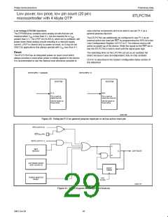
When the processor wakes up from Power Down mode, it will start
the oscillator immediately and begin execution when the oscillator is
stable. Oscillator stability is determined by counting 1024 CPU
clocks after start-up when one of the crystal oscillator configurations
is used, or 256 clocks after start-up for the internal RC or external
clock input configurations.
Power Reduction Modes
The 87LPC764 supports Idle and Power Down modes of power
reduction.
Idle Mode
The Idle mode leaves peripherals running in order to allow them to
activate the processor when an interrupt is generated. Any enabled
interrupt source or Reset may terminate Idle mode. Idle mode is
entered by setting the IDL bit in the PCON register (see Figure 19).
Some chip functions continue to operate and draw power during
Power Down mode, increasing the total power used during Power
Down. These include the Brownout Detect, Watchdog Timer, and
Comparators.
Power Down Mode
The Power Down mode stops the oscillator in order to absolutely
minimize power consumption. Power Down mode is entered by
setting the PD bit in the PCON register (see Figure 19).
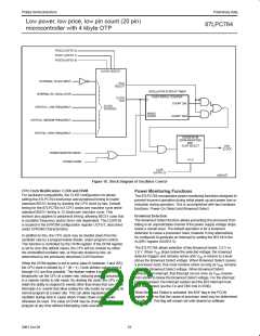
PCON
Address: 87h
Reset Value: S 30h for a Power On reset
S 20h for a Brownout reset
Not Bit Addressable
S 00h for other reset sources
7
6
5
4
3
2
1
0
SMOD1
SMOD0
BOF
POF
GF1
GF0
PD
IDL
BIT
SYMBOL
SMOD1
SMOD0
FUNCTION
PCON.7
PCON.6
When set, this bit doubles the UART baud rate for modes 1, 2, and 3.
This bit selects the function of bit 7 of the SCON SFR. When 0, SCON.7 is the SM0 bit. When 1,
SCON.7 is the FE (Framing Error) flag. See Figure 28 for additional information.
PCON.5
PCON.4
BOF
POF
Brown Out Flag. Set automatically when a brownout reset or interrupt has occurred. Also set at
power on. Cleared by software. Refer to the Power Monitoring Functions section for additional
information.
Power On Flag. Set automatically when a power-on reset has occurred. Cleared by software. Refer
to the Power Monitoring Functions section for additional information.
PCON.3
PCON.2
PCON.1
GF1
GF0
PD
General purpose flag 1. May be read or written by user software, but has no effect on operation.
General purpose flag 0. May be read or written by user software, but has no effect on operation.
Power Down control bit. Setting this bit activates Power Down mode operation. Cleared when the
Power Down mode is terminated (see text).
PCON.0
IDL
Idle mode control bit. Setting this bit activates Idle mode operation. Cleared when the Idle mode is
terminated (see text).
SU01475
Figure 19. Power Control Register (PCON)
24
2001 Oct 26

 NXP [ NXP ]