Philips Semiconductors
Preliminary data
Low power, low price, low pin count (20 pin)
microcontroller with 4 kbyte OTP
87LPC764
Oscillator
The 87LPC764 provides several user selectable oscillator options,
allowing optimization for a range of needs from high precision to
lowest possible cost. These are configured when the EPROM is
programmed. Basic oscillator types that are supported include: low,
medium, and high speed crystals, covering a range from 20 kHz to
20 MHz; ceramic resonators; and on-chip RC oscillator.
Low Frequency Oscillator Option
This option supports an external crystal in the range of 20 kHz to 100 kHz.
Table 5 shows capacitor values that may be used with a quartz crystal in this mode.
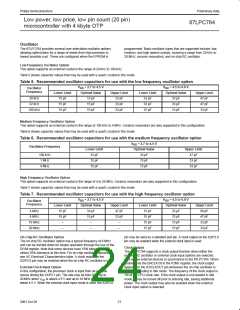
Table 5. Recommended oscillator capacitors for use with the low frequency oscillator option
V
DD
= 2.7 to 4.5 V
V
DD
= 4.5 to 6.0 V
Oscillator
Frequency
Lower Limit
15 pF
Optimal Value
15 pF
Upper Limit
33 pF
Lower Limit
33 pF
Optimal Value
33 pF
Upper Limit
47 pF
20 kHz
32 kHz
100 kHz
15 pF
15 pF
33 pF
33 pF
33 pF
47 pF
15 pF
15 pF
33 pF
15 pF
15 pF
33 pF
Medium Frequency Oscillator Option
This option supports an external crystal in the range of 100 kHz to 4 MHz. Ceramic resonators are also supported in this configuration.
Table 6 shows capacitor values that may be used with a quartz crystal in this mode.
Table 6. Recommended oscillator capacitors for use with the medium frequency oscillator option
V
DD
= 2.7 to 4.5 V
Oscillator Frequency
Lower Limit
33 pF
Optimal Value
33 pF
Upper Limit
47 pF
100 kHz
1 MHz
4 MHz
15 pF
15 pF
33 pF
15 pF
15 pF
33 pF
High Frequency Oscillator Option
This option supports an external crystal in the range of 4 to 20 MHz. Ceramic resonators are also supported in this configuration.
Table 7 shows capacitor values that may be used with a quartz crystal in this mode.
Table 7. Recommended oscillator capacitors for use with the high frequency oscillator option
V
DD
= 2.7 to 4.5 V
V
DD
= 4.5 to 6.0 V
Oscillator
Frequency
Lower Limit
Optimal Value
Upper Limit
Lower Limit
15 pF
Optimal Value
33 pF
Upper Limit
68 pF
4 MHz
8 MHz
15 pF
15 pF
–
33 pF
15 pF
–
47 pF
33 pF
–
15 pF
33 pF
47 pF
16 MHz
20 MHz
15 pF
15 pF
33 pF
–
–
–
15 pF
15 pF
33 pF
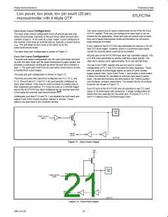
On-Chip RC Oscillator Option
pin may be used as a standard port pin. A clock output on the X2/P2.0
pin may be enabled when the external clock input is used.
The on-chip RC oscillator option has a typical frequency of 6 MHz
and can be divided down for slower operation through the use of the
DIVM register. Note that some devices have 10% tolerance and
others 25% tolerance at this time. For on-chip oscillator tolerance
see AC Electrical Characteristics table. A clock output on the
X2/P2.0 pin may be enabled when the on-chip RC oscillator is used.
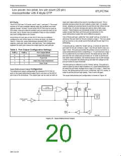
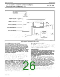
Clock Output
The 87LPC764 supports a clock output function when either the
on-chip RC oscillator or external clock input options are selected.
This allows external devices to synchronize to the 87LPC764. When
enabled, via the ENCLK bit in the P2M1 register, the clock output
appears on the X2/CLKOUT pin whenever the on-chip oscillator is
running, including in Idle mode. The frequency of the clock output is
1/6 of the CPU clock rate. If the clock output is not needed in Idle
mode, it may be turned off prior to entering Idle, saving additional
power. The clock output may also be enabled when the external
clock input option is selected.
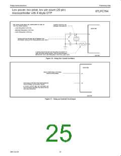
External Clock Input Option
In this configuration, the processor clock is input from an external
source driving the X1/P2.1 pin. The rate may be from 0 Hz up to
20 MHz when V is above 4.5 V and up to 10 MHz when V is
DD
DD
below 4.5 V. When the external clock input mode is used, the X2/P2.0
21
2001 Oct 26

 NXP [ NXP ]