Philips Semiconductors
Preliminary specification
80C51 8-bit microcontroller
8K/256 OTP, 8 channel 10 bit A/D, I2C, PWM,
capture/compare, high I/O, low voltage (2.7V–5.5V), low power
P87C552
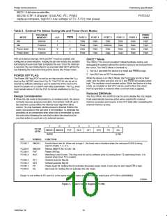
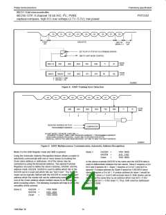
Table 2. External Pin Status During Idle and Power-Down Modes
PROGRAM
MEMORY
PWM0/
MODE
Idle
ALE
PSEN
PORT 0
Data
PORT 1
Data
PORT 2
Data
PORT 3
Data
PORT 4
Data
PWM1
High
High
High
High
Internal
1
1
0
0
1
1
0
0
Idle
External
Internal
Float
Data
Address
Data
Data
Data
Power-down
Power-down
Data
Data
Data
Data
External
Float
Data
Data
Data
Data
With an external interrupt, INT0 and INT1 must be enabled and
ONCE Mode
configured as level-sensitive. Holding the pin low restarts the oscillator
but bringing the pin back high completes the exit. Once the interrupt
is serviced, the next instruction to be executed after RETI will be the
one following the instruction that put the device into Power Down.
The ONCE (“On-Circuit Emulation”) Mode facilitates testing and
debugging of systems without the device having to be removed from
the circuit. The ONCE Mode is invoked by:
1. Pull ALE low while the device is in reset and PSEN is high;
2. Hold ALE low as RST is deactivated.
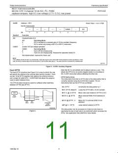
POWER OFF FLAG
The Power Off Flag (POF) is set by on-chip circuitry when the V
level on the 8XC552 rises from 0 to 5V. The POF bit can be set or
cleared by software allowing a user to determine if the reset is the
While the device is in ONCE Mode, the Port 0 pins go into a float
state, and the other port pins and ALE and PSEN are weakly pulled
high. The oscillator circuit remains active. While the device is in this
mode, an emulator or test CPU can be used to drive the circuit.
Normal operation is restored when a normal reset is applied.
CC
result of a power-on or a warm start after powerdown. The V level
CC
must remain above 3V for the POF to remain unaffected by the V
level.
CC
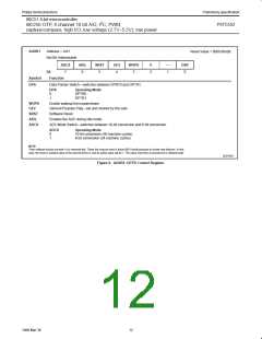
Reduced EMI Mode
Design Consideration
The ALE-Off bit, AO (AUXR.0) can be set to disable the ALE output.
It will automatically become active when required for external
memory accesses and resume to the OFF state after completing the
external memory access.
• When the idle mode is terminated by a hardware reset, the device
normally resumes program execution, from where it left off, up to
two machine cycles before the internal reset algorithm takes
control. On-chip hardware inhibits access to internal RAM in this
event, but access to the port pins is not inhibited. To eliminate the
possibility of an unexpected write when Idle is terminated by reset,
the instruction following the one that invokes Idle should not be
one that writes to a port pin or to external memory.
7
6
5
4
3
2
1
0
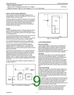
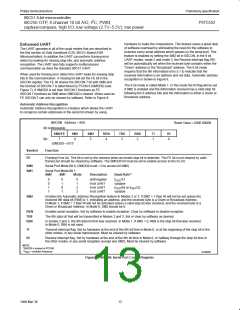
PCON
(87H)
SMOD1 SMOD0
(MSB)
POF
WLE
GF1
GF0
PD
IDL
(LSB)
BIT
SYMBOL FUNCTION
PCON.7
SMOD1
Double Baud rate bit. When set to logic 1, the baud rate is doubled when the serial port SIO0 is being
used in modes 1, 2, or 3.
PCON.6
PCON.5
PCON.4
SMOD0
POF
WLE
Selects SM0/FE for SCON.7 bit.
Power Off Flag
Watchdog Load Enable. This flag must be set by software prior to loading timer T3 (watchdog timer). It is
cleared when timer T3 is loaded.
PCON.3
PCON.2
PCON.1
PCON.0
GF1
GF0
PD
General-purpose flag bit.
General-purpose flag bit.
Power-down bit. Setting this bit activates the power-down mode. It can only be set if input EW is high.
Idle mode bit. Setting this bit activates the Idle mode.
IDL
If logic 1s are written to PD and IDL at the same time, PD takes precedence. The reset value of PCON is (00X00000).
SU00954
Figure 3. Power Control Register (PCON)
10
1999 Mar 30

 NXP [ NXP ]