Philips Semiconductors
Preliminary specification
80C51 8-bit microcontroller
8K/256 OTP, 8 channel 10 bit A/D, I2C, PWM,
capture/compare, high I/O, low voltage (2.7V–5.5V), low power
P87C552
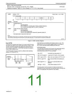
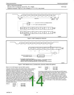
D0
D1
D2
D3
D4
D5
D6
D7
D8
START
BIT
DATA BYTE
ONLY IN
MODE 2, 3
STOP
BIT
SET FE BIT IF STOP BIT IS 0 (FRAMING ERROR)
SM0 TO UART MODE CONTROL
SCON
(98H)
SM0 / FE
SMOD1
SM1
SM2
POF
REN
WLE
TB8
GF1
RB8
GF0
TI
RI
PCON
(87H)
SMOD0
PD
IDL
0 : S0CON.7 = SM0
1 : S0CON.7 = FE
SU00982
Figure 8. UART Framing Error Detection
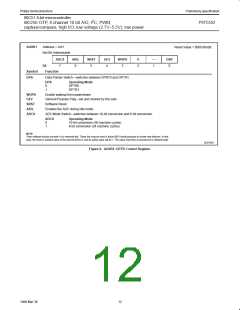
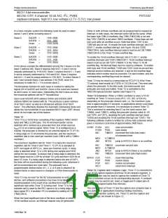
D0
D1
D2
D3
D4
D5
D6
D7
D8
SCON
(98H)
SM0
SM1
SM2
REN
1
TB8
X
RB8
TI
RI
1
1
1
0
1
RECEIVED ADDRESS D0 TO D7
PROGRAMMED ADDRESS
COMPARATOR
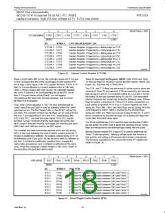
IN UART MODE 2 OR MODE 3 AND SM2 = 1:
INTERRUPT IF REN=1, RB8=1 AND “RECEIVED ADDRESS” = “PROGRAMMED ADDRESS”
– WHEN OWN ADDRESS RECEIVED, CLEAR SM2 TO RECEIVE DATA BYTES
– WHEN ALL DATA BYTES HAVE BEEN RECEIVED: SET SM2 TO WAIT FOR NEXT ADDRESS.
SU00045
Figure 9. UART Multiprocessor Communication, Automatic Address Recognition
Mode 0 is the Shift Register mode and SM2 is ignored.
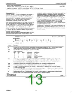
Slave 1
SADDR
SADEN
Given
=
=
=
1100 0000
1111 1110
1100 000X
Using the Automatic Address Recognition feature allows a master to
selectively communicate with one or more slaves by invoking the
Given slave address or addresses. All of the slaves may be
contacted by using the Broadcast address. Two special Function
Registers are used to define the slave’s address, SADDR, and the
address mask, SADEN. SADEN is used to define which bits in the
SADDR are to b used and which bits are “don’t care”. The SADEN
mask can be logically ANDed with the SADDR to create the “Given”
address which the master will use for addressing each of the slaves.
Use of the Given address allows multiple slaves to be recognized
while excluding others. The following examples will help to show the
versatility of this scheme:
In the above example SADDR is the same and the SADEN data is
used to differentiate between the two slaves. Slave 0 requires a 0 in
bit 0 and it ignores bit 1. Slave 1 requires a 0 in bit 1 and bit 0 is
ignored. A unique address for Slave 0 would be 1100 0010 since
slave 1 requires a 0 in bit 1. A unique address for slave 1 would be
1100 0001 since a 1 in bit 0 will exclude slave 0. Both slaves can be
selected at the same time by an address which has bit 0 = 0 (for
slave 0) and bit 1 = 0 (for slave 1). Thus, both could be addressed
with 1100 0000.
Slave 0
SADDR
SADEN
Given
=
=
=
1100 0000
1111 1101
1100 00X0
14
1999 Mar 30

 NXP [ NXP ]