Philips Semiconductors
Preliminary specification
80C51 8-bit microcontroller
8K/256 OTP, 8 channel 10 bit A/D, I2C, PWM,
capture/compare, high I/O, low voltage (2.7V–5.5V), low power
P87C552
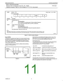
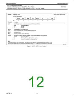
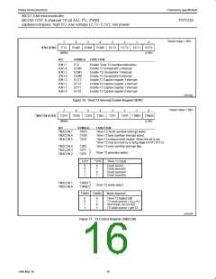
AUXR1
Address = A2H
Reset Value = 0000 00x0B
Not Bit Addressable
ADC8
AIDL
SRST
GF2
WUPD
0
—
1
DSP
Bit:
Function
Data Pointer Switch—switches between DPRT0 and DPTR1.
7
6
5
4
3
2
0
Symbol
DPS
DPS
0
1
Operating Mode
DPTR0
DPTR1
WUPD
GF2
Enable wakeup from powerdown.
General Purpose Flag—set and cleared by the user.
Software Reset
SRST
AIDL
ADC8
Enables the ADC during idle mode.
ADC Mode Switch—switches between 10-bit conversion and 8-bit conversion.
ADC8
Operating Mode
0
1
10-bit conversion (50 machine cycles)
8-bit conversion (24 machine cycles)
NOTE:
*User software should not write 1s to reserved bits. These bits may be used in future 8051 family products to invoke new features. In that
case, the reset or inactive value of the new bit will be 0, and its active value will be 1. The value read from a reserved bit is indeterminate.
SU01081
Figure 6. AUXR1: DPTR Control Register
12
1999 Mar 30

 NXP [ NXP ]