Philips Semiconductors
Preliminary specification
80C51 8-bit microcontroller
8K/256 OTP, 8 channel 10 bit A/D, I2C, PWM,
capture/compare, high I/O, low voltage (2.7V–5.5V), low power
P87C552
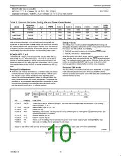
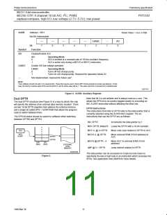
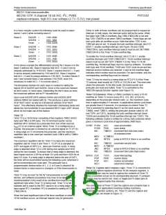
AUXR
Address = 8EH
Reset Value = xxxx x110B
Not Bit Addressable
—
—
6
—
5
—
4
—
3
LVADC
–
AO
Bit:
Function
Disable/Enable ALE
7
2
1
0
Symbol
AO
AO
0
1
Operating Mode
ALE is emitted at a constant rate of 1/6 the oscillator frequency.
ALE is active only during a MOVX or MOVC instruction.
LVADC
Enable A/D low voltage operation
LVADC
Operating Mode
0
1
Turns off A/D charge pump.
Turns on A/D charge pump. Required for operation below 4V.
—
Not implemented, reserved for future use*.
NOTE:
*User software should not write 1s to reserved bits. These bits may be used in future 8051 family products to invoke new features. In that
case, the reset or inactive value of the new bit will be 0, and its active value will be 1. The value read from a reserved bit is indeterminate.
SU01115
Figure 4. AUXR: Auxiliary Register
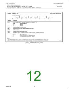
Note that bit 2 is not writable and is always read as a zero. This
allows the DPS bit to be quickly toggled simply by executing an
INC AUXR1 instruction without affecting the other bits.
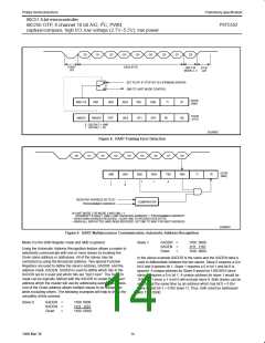
Dual DPTR
The dual DPTR structure (see Figure 5) is a way by which the chip
will specify the address of an external data memory location. There
are two 16-bit DPTR registers that address the external memory,
and a single bit called DPS = AUXR1/bit0 that allows the program
code to switch between them.
DPTR Instructions
The instructions that refer to DPTR refer to the data pointer that is
currently selected using the AUXR1/bit 0 register. The six
instructions that use the DPTR are as follows:
The DPS bit status should be saved by software when switching
between DPTR0 and DPTR1.
INC DPTR
Increments the data pointer by 1
MOV DPTR, #data16 Loads the DPTR with a 16-bit constant
MOV A, @ A+DPTR
MOVX A, @ DPTR
Move code byte relative to DPTR to ACC
DPS
BIT0
Move external RAM (16-bit address) to
ACC
AUXR1
DPTR1
DPTR0
MOVX @ DPTR , A
JMP @ A + DPTR
Move ACC to external RAM (16-bit
address)
DPH
(83H)
DPL
(82H)
EXTERNAL
DATA
MEMORY
Jump indirect relative to DPTR
SU00745A
The data pointer can be accessed on a byte-by-byte basis by
specifying the low or high byte in an instruction which accesses the
SFRs. See application note AN458 for more details.
Figure 5.
11
1999 Mar 30

 NXP [ NXP ]