Philips Semiconductors
Preliminary specification
80C51 8-bit microcontroller
8K/256 OTP, 8 channel 10 bit A/D, I2C, PWM,
capture/compare, high I/O, low voltage (2.7V–5.5V), low power
P87C552
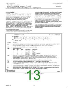
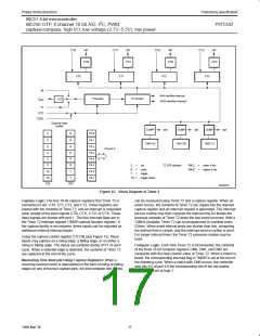
hardware to make the comparisons. This feature saves a great deal
of software overhead by eliminating the need for the software to
examine every serial address which passes by the serial port. This
feature is enabled by setting the SM2 bit in S0CON. In the 9 bit
UART modes, mode 2 and mode 3, the Receive Interrupt flag (RI)
will be automatically set when the received byte contains either the
“Given” address or the “Broadcast” address. The 9 bit mode
requires that the 9th information bit is a 1 to indicate that the
received information is an address and not data. Automatic address
recognition is shown in Figure 9.
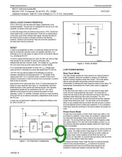
Enhanced UART
The UART operates in all of the usual modes that are described in
the first section of Data Handbook IC20, 80C51-Based 8-Bit
Microcontrollers. In addition the UART can perform framing error
detect by looking for missing stop bits, and automatic address
recognition. The UART also fully supports multiprocessor
communication as does the standard 80C51 UART.
When used for framing error detect the UART looks for missing stop
bits in the communication. A missing bit will set the FE bit in the
S0CON register. The FE bit shares the S0CON.7 bit with SM0 and
the function of S0CON.7 is determined by PCON.6 (SMOD0) (see
Figure 7). If SMOD0 is set then S0CON.7 functions as FE.
The 8 bit mode is called Mode 1. In this mode the RI flag will be set
if SM2 is enabled and the information received has a valid stop bit
following the 8 address bits and the information is either a Given or
Broadcast address.
S0CON.7 functions as SM0 when SMOD0 is cleared. When used as
FE S0CON.7 can only be cleared by software. Refer to Figure 8.
Automatic Address Recognition
Automatic Address Recognition is a feature which allows the UART
to recognize certain addresses in the serial bit stream by using
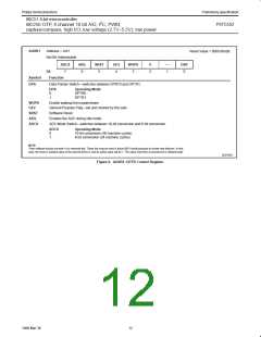
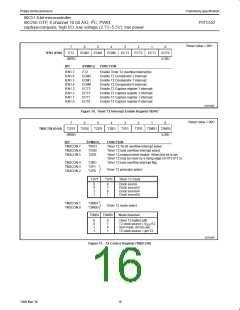
S0CON Address = 98H
Reset Value = 0000 0000B
Bit Addressable
SM0/FE
SM1
SM2
REN
TB8
RB8
Tl
Rl
Bit:
7
6
5
4
3
2
1
0
(SMOD0 = 0/1)*
Symbol
FE
Function
Framing Error bit. This bit is set by the receiver when an invalid stop bit is detected. The FE bit is not cleared by valid
frames but should be cleared by software. The SMOD0 bit must be set to enable access to the FE bit.
SM0
SM1
Serial Port Mode Bit 0, (SMOD0 must = 0 to access bit SM0)
Serial Port Mode Bit 1
SM0
SM1
Mode
Description
Baud Rate**
f /12
OSC
0
0
1
1
0
1
0
1
0
1
2
3
shift register
8-bit UART
9-bit UART
9-bit UART
variable
/64 or f
f
/32
OSC
OSC
variable
SM2
Enables the Automatic Address Recognition feature in Modes 2 or 3. If SM2 = 1 then Rl will not be set unless the
received 9th data bit (RB8) is 1, indicating an address, and the received byte is a Given or Broadcast Address.
In Mode 1, if SM2 = 1 then Rl will not be activated unless a valid stop bit was received, and the received byte is a
Given or Broadcast Address. In Mode 0, SM2 should be 0.
REN
TB8
RB8
Enables serial reception. Set by software to enable reception. Clear by software to disable reception.
The 9th data bit that will be transmitted in Modes 2 and 3. Set or clear by software as desired.
In modes 2 and 3, the 9th data bit that was received. In Mode 1, if SM2 = 0, RB8 is the stop bit that was received.
In Mode 0, RB8 is not used.
Tl
Transmit interrupt flag. Set by hardware at the end of the 8th bit time in Mode 0, or at the beginning of the stop bit in the
other modes, in any serial transmission. Must be cleared by software.
Rl
Receive interrupt flag. Set by hardware at the end of the 8th bit time in Mode 0, or halfway through the stop bit time in
the other modes, in any serial reception (except see SM2). Must be cleared by software.
NOTE:
*SMOD0 is located at PCON6.
**f = oscillator frequency
OSC
SU00981
Figure 7. S0CON: Serial Port Control Register
13
1999 Mar 30

 NXP [ NXP ]