P82B715
NXP Semiconductors
I2C-bus extender
3.3 V
R1
R2
R3
C3
FRU 1
Sx
Lx
Lx
Lx
Lx
Sx
Sx
Sx
ShMM
BUFFER
BUFFER
µC
µC
µC
1
C1
C2
R3
C3
FRU 2
BUFFER
common Lx node
radial traces
2
R3
C3
FRU 16
BUFFER
16
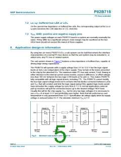
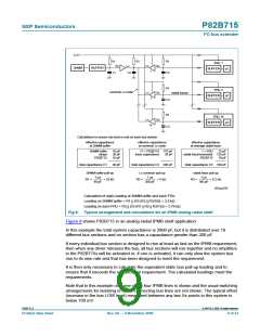
Calculations to ensure rise time is met on each bus section:
effective capacitance
at ShMM buffer
effective capacitance
at common Lx node
effective capacitance
at average radial trace
ShMM buffer
strays
10 pF
20 pF
10 pF
17 × P82B715 170 pF
trace capacitance 30 pF
1 × FRU
radial trace/connector 125 pF
P82B715 10 pF
25 pF
P82B715
total capacitance C1
40 pF
total capacitance C2 200 pF
total capacitance C3 160 pF
ShMM buffer pull-up
Lx common pull-up
radial trace pull-up
1 µs
1 µs
1 µs
R1 =
= 25 kΩ
R2 =
= 5 kΩ
R3 =
= 6.2 kΩ
40 pF
200 pF
160 pF
002aad708
Calculation of static loading at ShMM buffer and each FRU:
Loading on ShMM buffer = R1 || {10 (R2 || R3/16)} = 3.5 kΩ
Loading on each FRU = R3 || {10 (R1 || R2 || R3/15)} = 3.76 kΩ
Fig 8. Typical arrangement and calculations for an IPMB analog radial shelf
Figure 8 shows P82B715 in an analog radial IPMB shelf application.
In this example the total system capacitance is 2800 pF, but it is distributed over 18
different bus sections and no section has a capacitance greater than 200 pF.
If every individual bus section is designed to rise at least as fast as the IPMB requirement,
then when any driver releases the bus, all bus sections will rise together and no amplifiers
in the P82B715s will be activated or, if one is activated, it can only slow the system bus
rise to its own rate and that has been designed to meet the requirement.
It is then only necessary to calculate the equivalent static bus pull-up loading and to
ensure that it exceeds the specification requirement. The calculated loadings meet the
requirements.
Note that in this example only one of the four IPMB lines is shown and the usual switching
arrangements for isolating or cross-connecting bus lines are not shown. The typical offset
(increase in the bus LOW level) measured between any two Sx points in this system is
below 100 mV.
P82B715_8
© NXP B.V. 2009. All rights reserved.
Product data sheet
Rev. 08 — 9 November 2009
9 of 23

 NXP [ NXP ]