P82B715
NXP Semiconductors
I2C-bus extender
9. Limiting values
Table 4.
Limiting values
In accordance with the Absolute Maximum Rating System (IEC 60134).
Symbol Parameter
Conditions
Min
−0.3
0
Max
+12
VCC
VCC
60
Unit
V
[1]
[1]
[1]
VCC
Vbus
Vbuff
I
supply voltage
voltage range I2C-bus, SCL or SDA
voltage range buffered bus
DC current (any pin)
V
0
V
-
mA
mW
°C
°C
Ptot
Tstg
Tamb
total power dissipation
storage temperature
-
300
+125
+85
−55
−40
ambient temperature
operating
[1] Voltages with respect to GND.
The bus voltages quoted are DC voltages and are allowed to be exceeded during any negative transient
undershoot that may be generated by normal operation of P82B715, P82B96 or PCA9600 when any of
those parts are driving long PCB traces, wiring or cables. The Lx/Sx pins have internal protective diodes to
GND that will conduct when the applied bus voltage exceeds approximately −0.6 V and these diodes will
limit the amplitude of the negative undershoot. If required, fitting additional Schottky diodes such as
BAT54A at Sx/Sy may be used to further ensure any undershoot at these pins does not cause conduction of
the diodes inside other ICs connected to Sx/Sy.
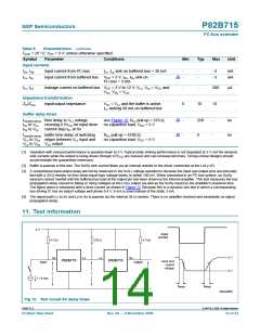
10. Characteristics
Table 5.
Characteristics
Tamb = 25 °C; VCC = 5 V; unless otherwise specified.
Symbol
Parameter
Conditions
operating
Min
Typ
Max
Unit
Power supply
[1]
VCC
ICC
supply voltage
supply current
4.5
-
12
-
V
-
-
-
14
15
22
mA
mA
mA
VCC = 12 V
both I2C-bus inputs LOW; both
buffered outputs sinking 30 mA
-
-
Drive currents
ISx, ISy
output sink on I2C-bus
[2]
VCC > 3 V; VSx, VSy LOW = 0.4 V;
VLx, VLy LOW on buffered bus = 0.3 V;
ILx, ILy = −3 mA
3
-
-
-
-
mA
mA
ILx, ILy
output sink on buffered bus
VLx, VLy LOW = 0.4 V;
30
V
Sx, VSy LOW on I2C-bus = 0.3 V
Derated dynamic drive currents for VCC < 4.5 V[1]
ILx, ILy
output sink on buffered bus
VCC > 3 V;
24
24
-
-
-
-
mA
mA
VLx, VLy LOW = 0.4 V to 1.5 V;
I
Sx, ISy sinking on I2C-bus < −4 mA
VCC > 3 V;
VLx, VLy LOW = 1.5 V to VCC
I
;
Sx, ISy sinking on I2C-bus = −7 mA
P82B715_8
© NXP B.V. 2009. All rights reserved.
Product data sheet
Rev. 08 — 9 November 2009
13 of 23

 NXP [ NXP ]