KMA220
NXP Semiconductors
Dual channel programmable angle sensor
13. Programming
13.1 General description
Each channel of the KMA220 provides an OWI to enable programming of the device
which uses pin OUT1/DATA1 and pin OUT2/DATA2 bidirectionally.
In general the device runs in analog output mode, the normal operation mode.
The embedded programming data configures this mode. After a power-on reset once time
ton has elapsed,it starts. In this mode, the magnetic field angle is converted into the
corresponding output voltage per channel.
A second mode, the command mode enables programming. In this mode, the customer
can adjust all required parameters (for example zero angle and angular range) to meet the
application requirements. After enabling the internal charge pump and waiting for tcp, the
data is stored in the non-volatile memory. After changing the contents of the memory,
recalculate and write the checksum (see Section 13.4).
In order to enter the command mode, send a specific command sequence after
a power-on reset and during the time slot tcmd(ent). The external source used to send the
command sequence must overdrive the output buffers of the KMA220. In doing so, it
provides current Iod. This signature can be sent to each channel separately or in parallel.
During communication, the channels of the KMA220 are always the slaves and the
external programming hardware is always the master. Figure 12 illustrates the structure of
the OWI data format.
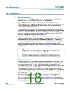
write
IDLE START COMMAND DATA BYTE 1 DATA BYTE 2 STOP
IDLE
read
IDLE START COMMAND HANDOVER DATA BYTE 1 DATA BYTE 2 TAKEOVER STOP IDLE
001aag742
Fig 12. OWI data format
The master provides the start condition, which is a rising edge after a LOW level. Then
a command byte which can be either a read or a write command is sent. Depending on
the command, the master or the slave has to send the data immediately after the
command sequence. If there is a read command, an additional handover or takeover bit is
inserted before and after the data bytes. The master must close each communication with
a stop condition. If the slave does not receive a rising edge for a time longer than tto,
a time-out condition occurs. The bus is reset to the idle state and waits for a start condition
and a new command. This behavior can be used to synchronize the device regardless of
the previous state.
All communication is based on this structure (see Figure 12), even for entering the
command mode. The customer can access the non-volatile memory, CTRL1,
TESTCTRL0 and SIGNATURE registers (described in Section 13.5). Only a power-on
reset leaves the command mode. A more detailed description of the programming is given
in the next sections.
KMA220
All information provided in this document is subject to legal disclaimers.
© NXP B.V. 2012. All rights reserved.
Product data sheet
Rev. 1 — 24 May 2012
18 of 36

 NXP [ NXP ]