KMA220
NXP Semiconductors
Dual channel programmable angle sensor
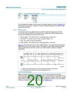
13.3.2 Read access
Perform the following procedure, to read data from the sensor:
1. Start condition: The master drives a rising edge after a LOW level
2. Command: The master sends a read command (CMD0 = 1)
3. Handover: The master sends a handover bit, that is a logic 0 and disables the output
after a three-quarter bit period
4. Takeover: The slave drives a LOW level after the falling edge for ttko(slv)
5. Data: The slave sends two data bytes
6. Handover: The slave sends a handover bit, that is a logic 0 and disables the output
after a three-quarter bit period
7. Takeover: The master drives a LOW level after the falling edge for ttko(mas)
8. Stop condition: The master drives a rising edge after a LOW level
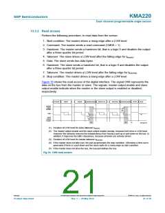
Figure 16 shows the read access of the digital interface. The signal OWI represents the
data on the bus from the master or slave. The signals: master output enable and slave
output enable indicate when the master or the slave output is enabled or disabled,
respectively.
START
CMD7
CMD0
HANDSHAKE
RDATA15
RDATA0
HANDSHAKE
STOP
IDLE
master
output
enable
(3)
OWI
(5)
(1)
slave
output
enable
(2)
(2)
(4)
001aag744
(1) Duration of LOW level for slave takeover ttko(slv)
.
(2) The master output enable and the slave output enable overlap, because both drive a LOW level.
However this behavior ensures the independency from having a pull-up or pull-down on the bus. In
addition, it improves the EMC robustness, because all levels are actively driven.
(3) Duration of LOW level for master takeover ttko(mas)
.
(4) If the master does not take over, the pull-up generates the stop condition. Otherwise a time-out is
generated if there is a pull-down and the slave waits for a rising edge as start condition.
(5) If the master does not drive the bus, the bus-pull defines the bus.
Fig 16. OWI read access
KMA220
All information provided in this document is subject to legal disclaimers.
© NXP B.V. 2012. All rights reserved.
Product data sheet
Rev. 1 — 24 May 2012
21 of 36

 NXP [ NXP ]