KMA220
NXP Semiconductors
Dual channel programmable angle sensor
12. Definition of errors
12.1 General
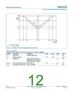
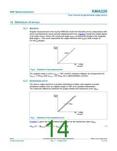
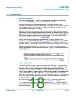
Angular measurement errors by the KMA220 result from linearity errors, temperature drift
errors and hysteresis errors and die displacement error. Figure 6 shows the output signal
of an ideal sensor, where the measured angle meas corresponds ideally to the magnetic
field angle . This curve represents the angle reference line ref() with a slope of
0.5 %VDD/degree.
φ
meas
(deg)
φ
ref
(α)
α (deg)
180
001aag812
Fig 6. Definition of the reference line
The angular range is set to max = 180 and the clamping voltages are programmed to
(CL)l = 5 %VDD and V(CL)u = 95 %VDD for a valid definition of errors.
V
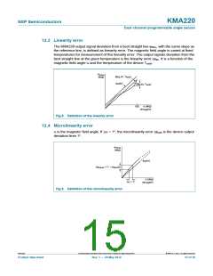
12.2 Hysteresis error
The device output performs a positive (clockwise) rotation and negative (counter
clockwise) rotation over an angular range of 180 at a constant temperature.
The maximum difference between the angles defines the hysteresis error hys
.
φ
meas
(deg)
Δφ
hys
α (deg)
180
001aag813
Fig 7. Definition of the hysteresis error
Equation 1 gives the mathematical description for the hysteresis value hys
:
hys() = meas( 180) – meas( 0)
(1)
KMA220
All information provided in this document is subject to legal disclaimers.
© NXP B.V. 2012. All rights reserved.
Product data sheet
Rev. 1 — 24 May 2012
14 of 36

 NXP [ NXP ]