KMA220
NXP Semiconductors
Dual channel programmable angle sensor
13.3.3 Entering the command mode
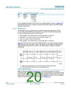
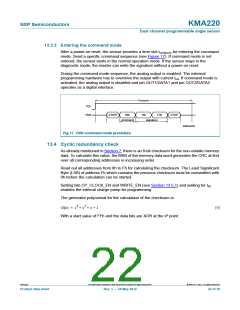
After a power-on reset, the sensor provides a time slot tcmd(ent) for entering the command
mode. Send a specific command sequence (see Figure 17). If command mode is not
entered, the sensor starts in the normal operation mode. If the sensor stays in the
diagnostic mode, the master can write the signature without a power-on reset.
During the command mode sequence, the analog output is enabled. The external
programming hardware has to overdrive the output with current Iod. If command mode is
activated, the analog output is disabled and pin OUT1/DATA1 and pin OUT2/DATA2
operates as a digital interface.
t
cmd(ent)
V
DD
OWI
START
94h
16h
F4h
STOP
command
signature
008aaa263
Fig 17. OWI command mode procedure
13.4 Cyclic redundancy check
As already mentioned in Section 7, there is an 8-bit checksum for the non-volatile memory
data. To calculate this value, the MSB of the memory data word generates the CRC at first
over all corresponding addresses in increasing order.
Read out all addresses from 8h to Fh for calculating the checksum. The Least Significant
Byte (LSB) of address Fh which contains the previous checksum must be overwritten with
0h before the calculation can be started.
Setting bits CP_CLOCK_EN and WRITE_EN (see Section 13.5.1) and waiting for tcp
enables the internal charge pump for programming.
The generator polynomial for the calculation of the checksum is:
G(x) = x8 + x2 + x + 1
(9)
With a start value of FFh and the data bits are XOR at the x8 point.
KMA220
All information provided in this document is subject to legal disclaimers.
© NXP B.V. 2012. All rights reserved.
Product data sheet
Rev. 1 — 24 May 2012
22 of 36

 NXP [ NXP ]