ISP1160
Embedded USB Host Controller
Philips Semiconductors
Table 43: HcµPInterrupt register: bit description…continued
Bit
Symbol
Description
2
AllEOT
0 — no event
Interrupt
1 — implies that data transfer has been completed via PIO transfer
or DMA transfer. Occurrence of internal or external EOT will set
this bit.
1
0
ATLInt
0 — no event
1 — implies that the microprocessor must read ATL data from the
HC. This requires that the HcBufferStatus register must first be
read. The time for this interrupt depends on the number of clocks
bit set for USB activities in each ms.
SOFITLInt 0 — no event
1 — implies that SOF indicates the 1 ms mark. The ITL buffer that
the HC has handled must be read. To know the ITL buffer status,
the HcBufferStatus register must first be read. This is for the
microprocessor to get ISO data to or from the HC. For more
information, see the 6th paragraph in Section 9.5.
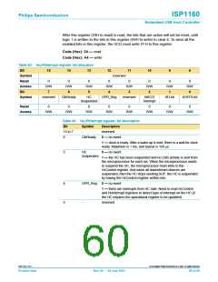
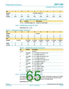
10.4.5 HcµPInterruptEnable register (R/W: 25H/A5H)
The bits 6:0 in this register are the same as those in the HcµPInterrupt register. They
are used together with bit 0 of the HcHardwareConfiguration register to enable or
disable the bits in the HcµPInterrupt register.
On power-on, all bits in this register are masked with logic 0. This means no interrupt
request output on the interrupt pin INT can be generated.
When the bit is set to logic 1, the interrupt for the bit is not masked but enabled.
Code (Hex): 25 — read
Code (Hex): A5 — write
Table 44: HcµPInterruptEnable register: bit allocation
Bit
15
14
13
12
11
10
9
8
Symbol
Reset
Access
Bit
reserved
0
R/W
0
R/W
0
R/W
5
0
R/W
4
0
R/W
3
0
R/W
2
0
R/W
1
0
R/W
0
7
6
Symbol
reserved
ClkReady
HC
OPR
reserved
EOT
ATL
SOF
Suspended
Enable
Interrupt
Enable
Interrupt
Enable
Interrupt
Enable
Interrupt
Enable
Reset
0
0
0
0
0
0
0
0
Access
R/W
R/W
R/W
R/W
R/W
R/W
R/W
R/W
9397 750 11371
© Koninklijke Philips Electronics N.V. 2003. All rights reserved.
Product data
Rev. 04 — 04 July 2003
61 of 88

 NXP [ NXP ]