ISP1160
Embedded USB Host Controller
Philips Semiconductors
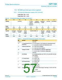
10.4 HC DMA and interrupt control registers
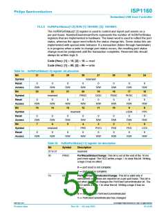
10.4.1 HcHardwareConfiguration register (R/W: 20H/A0H)
Code (Hex): 20 — read
Code (Hex): A0 — write
Table 36: HcHardwareConfiguration register: bit allocation
Bit
15
14
13
12
11
10
9
8
Symbol
reserved
2_Down
stream
Suspend
ClkNotStop
AnalogOC
Enable
reserved DACKMode
Port15K
resistorsel
Reset
Access
Bit
0
R/W
7
0
R/W
6
0
R/W
5
0
R/W
4
0
R/W
3
0
R/W
2
0
R/W
1
0
R/W
0
Symbol
EOTInput
Polarity
DACKInput
Polarity
DREQ
Output
Polarity
DataBusWidth[1:0]
Interrupt
Output
Polarity
Interrupt
PinTrigger
InterruptPin
Enable
Reset
0
0
1
0
1
0
0
0
Access
R/W
R/W
R/W
R/W
R/W
R/W
R/W
R/W
Table 37: HcHardwareConfiguration register: bit description
Bit
Symbol
Description
15 to 13 -
reserved
12
11
10
2_DownstreamPort15K 0 — use external 15 kΩ resistors for downstream ports
resistorsel
1 — use built-in resistors for downstream ports
SuspendClkNotStop
AnalogOCEnable
0 — clock can be stopped
1 — clock can not be stopped
0 — use external OC detection; digital input
1 — use on-chip OC detection; analog input
reserved
9
8
-
DACKMode
0 — normal operation; pin DACK_N is used with read and
write signals
1 — reserved
7
EOTInputPolarity
0 — active LOW
1 — active HIGH
6
DACKInputPolarity
DREQOutputPolarity
DataBusWidth[1:0]
0 — active LOW
1 — reserved
5
0 — active LOW
1 — active HIGH
4 to 3
These bits are fixed at logic 0 and logic 1 for the ISP1160.
01 — 16 bits
Others — reserved
9397 750 11371
© Koninklijke Philips Electronics N.V. 2003. All rights reserved.
Product data
Rev. 04 — 04 July 2003
57 of 88

 NXP [ NXP ]