ISP1160
Embedded USB Host Controller
Philips Semiconductors
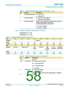
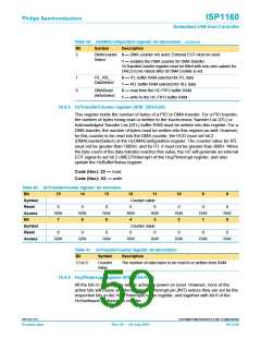
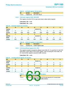
Table 39: HcDMAConfiguration register: bit description…continued
Bit
Symbol
Description
2
DMACounter 0 — DMA counter not used. External EOT must be used
Select
1 — enables the DMA counter for DMA transfer.
HcTransferCounter register must be filled with non-zero values for
DREQ to be raised after bit DMA Enable is set.
1
0
ITL_ATL_
DataSelect
0 — ITL buffer RAM selected for ITL data
1 — ATL buffer RAM selected for ATL data
0 — read from the HC FIFO buffer RAM
1 — write to the HC FIFO buffer RAM
DMARead
WriteSelect
10.4.3 HcTransferCounter register (R/W: 22H/A2H)
This register holds the number of bytes of a PIO or DMA transfer. For a PIO transfer,
the number of bytes being read or written to the Isochronous Transfer List (ITL) or
Acknowledged Transfer List (ATL) buffer RAM must be written into this register. For a
DMA transfer, the number of bytes must be written into this register as well. However,
for this counter to be read into the DMA counter, the HCD must set bit 2
(DMACounterSelect) of the HcDMAConfiguration register. The counter value for ATL
must not be greater than 1000H, and for ITL it must not be greater than 800H. When
the byte count of the data transfer reaches this value, the HC will generate an internal
EOT signal to set bit 2 (AllEOTInterrupt) of the HcµPInterrupt register, and also
update the HcBufferStatus register.
Code (Hex): 22 — read
Code (Hex): A2 — write
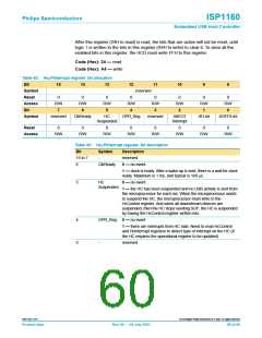
Table 40: HcTransferCounter register: bit allocation
Bit
15
14
13
12
11
10
9
8
Symbol
Reset
Access
Bit
Counter value
0
R/W
7
0
R/W
6
0
R/W
5
0
R/W
4
0
R/W
3
0
R/W
2
0
R/W
1
0
R/W
0
Symbol
Reset
Access
Counter value
0
0
0
0
0
0
0
0
R/W
R/W
R/W
R/W
R/W
R/W
R/W
R/W
Table 41: HcTransferCounter register: bit description
Bit
Symbol
Description
The number of data bytes to be read to or written from RAM.
15 to 0
Counter
value
10.4.4 HcµPInterrupt register (R/W: 24H/A4H)
All the bits in this register will be active on power-on reset. However, none of the
active bits will cause an interrupt on the interrupt pin (INT) unless they are set by the
respective bits in the HcµPInterruptEnable register, and together with bit 0 of the
HcHardwareConfiguration register.
9397 750 11371
© Koninklijke Philips Electronics N.V. 2003. All rights reserved.
Product data
Rev. 04 — 04 July 2003
59 of 88

 NXP [ NXP ]