ISP1160
Embedded USB Host Controller
Philips Semiconductors
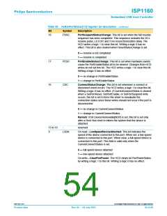
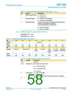
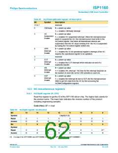
Table 37: HcHardwareConfiguration register: bit description…continued
Bit
Symbol
Description
2
InterruptOutputPolarity 0 — active LOW
1 — active HIGH
1
0
InterruptPinTrigger
0 — interrupt is level-triggered
1 — interrupt is edge-triggered
InterruptPinEnable
This bit is used as pin INT’s master interrupt enable and
should be used together with register
HcµPInterruptEnable to enable pin INT.
0 — pin INT is disabled
1 — pin INT is enabled
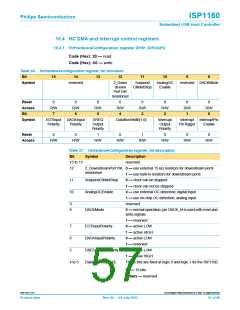
10.4.2 HcDMAConfiguration register (R/W: 21H/A1H)
Code (Hex): 21 — read
Code (Hex): A1 — write
Table 38: HcDMAConfiguration register: bit allocation
Bit
15
14
13
12
11
10
9
8
Symbol
Reset
Access
Bit
reserved
0
R/W
0
R/W
6
0
R/W
5
0
R/W
4
0
R/W
3
0
R/W
2
0
R/W
0
R/W
7
1
0
Symbol
reserved
BurstLen[1:0]
DMA
Enable
reserved
DMA
Counter
Select
ITL_ATL_
DataSelect WriteSelect
DMARead
Reset
0
0
0
0
0
0
0
0
Access
R/W
R/W
R/W
R/W
R/W
R/W
R/W
R/W
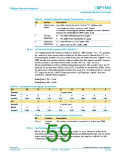
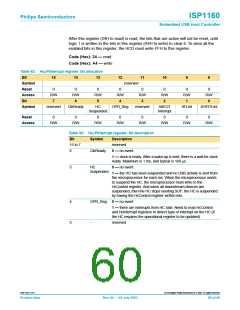
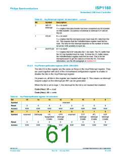
Table 39: HcDMAConfiguration register: bit description
Bit
Symbol
Description
15 to 7
6 to 5
-
reserved
BurstLen[1:0] 00 — single-cycle burst DMA
01 — 4-cycle burst DMA
10 — 8-cycle burst DMA
11 — reserved
4
3
DMAEnable
-
0 — DMA is terminated
1 — DMA is enabled
This bit will be reset to logic 0 when DMA transfer is completed.
reserved
9397 750 11371
© Koninklijke Philips Electronics N.V. 2003. All rights reserved.
Product data
Rev. 04 — 04 July 2003
58 of 88

 NXP [ NXP ]