ISP1160
Embedded USB Host Controller
Philips Semiconductors
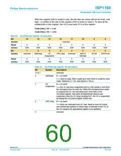
After this register (24H to read) is read, the bits that are active will not be reset, until
logic 1 is written to the bits in this register (A4H to write) to clear it. To clear all the
enabled bits in this register, the HCD must write FFH to this register.
Code (Hex): 24 — read
Code (Hex): A4 — write
Table 42: HcµPInterrupt register: bit allocation
Bit
15
14
13
12
11
10
9
8
Symbol
Reset
Access
Bit
reserved
0
R/W
0
R/W
0
R/W
5
0
R/W
4
0
R/W
0
R/W
2
0
R/W
1
0
R/W
7
6
3
0
Symbol
reserved
ClkReady
HC
OPR_Reg
reserved
AIIEOT
ATLInt
SOFITLInt
Suspended
Interrupt
Reset
0
0
0
0
0
0
0
0
Access
R/W
R/W
R/W
R/W
R/W
R/W
R/W
R/W
Table 43: HcµPInterrupt register: bit description
Bit
Symbol
-
Description
reserved
15 to 7
6
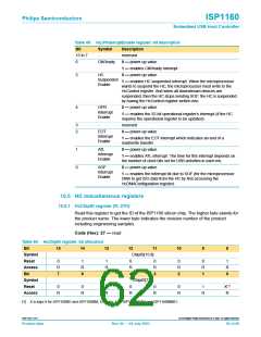
ClkReady
0 — no event
1 — clock is ready. After a wake-up is sent, there is a wait for clock
ready. Maximum is 1 ms, and typical is 160 µs.
5
HC
0 — no event
Suspended
1 — the HC has been suspended and no USB activity is sent from
the microprocessor for each ms. When the microprocessor wants
to suspend the HC, the microprocessor must write to the
HcControl register. And when all downstream devices are
suspended, then the HC stops sending SOF; the HC is suspended
by having the HcControl register written into.
4
3
OPR_Reg 0 — no event
1 — there are interrupts from HC side. Need to read HcControl
and HcInterrupt registers to detect type of interrupt on the HC (if
the HC requires the operational register to be updated).
-
reserved
9397 750 11371
© Koninklijke Philips Electronics N.V. 2003. All rights reserved.
Product data
Rev. 04 — 04 July 2003
60 of 88

 NXP [ NXP ]