ISP1160
Embedded USB Host Controller
Philips Semiconductors
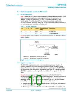
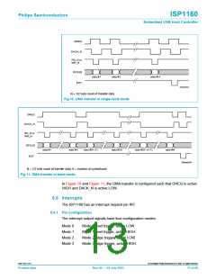
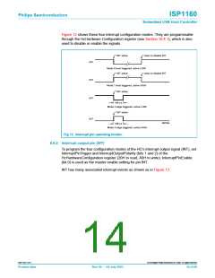
Figure 12 shows these four interrupt configuration modes. They are programmable
through the HcHardware Configuration register (see Section 10.4.1), which is also
used to disable or enable the signals.
clear or disable INT
INT active
INT
INT
Mode 0 level triggered, active LOW
clear or disable INT
INT active
Mode 1 level triggered, active HIGH
INT active
INT
INT
166 ns
Mode 2 edge triggered, active LOW
INT active
MGT944
166 ns
Mode 3 edge triggered, active HIGH
Fig 12. Interrupt pin operating modes.
8.6.2 Interrupt output pin (INT)
To program the four configuration modes of the HC’s interrupt output signal (INT), set
InterruptPinTrigger and InterruptOutputPolarity (bits 1 and 2) of the
HcHardwareConfiguration register (20H to read, A0H to write). InterruptPinEnable
(bit 0) is used as the master enable setting for pin INT.
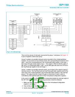
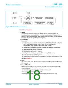
INT has many associated interrupt events as shown as in Figure 13.
9397 750 11371
© Koninklijke Philips Electronics N.V. 2003. All rights reserved.
Product data
Rev. 04 — 04 July 2003
14 of 88

 NXP [ NXP ]