Philips Semiconductors
Product specification
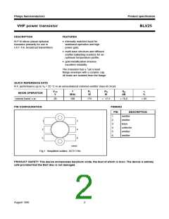
VHF power transistor
BLV25
APPLICATION INFORMATION
R.F. performance in narrow band c.w. operation (common-emitter class-B circuit) Th = 25 °C
f
VCE
V
PL
W
PS
W
Gp
dB
IC
A
η
%
MHz
108
28
175
<
17,5
>
10,0
11,0
<
9,6
>
65
70
typ.
13,9 typ.
typ.
8,9 typ.
C12
handbook, full pagewidth
C4
C5
L2
L7
L6
50 Ω
T.U.T.
C7
L1
C15
C16
50 Ω
C9
C13
L5
C1
C2
C3
L3
C6
L4
L8
L9
+V
CC
R1
C8
C10
C11
C14
MGP299
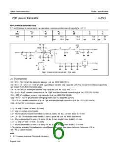
Fig.7 Class-B test circuit at f = 108 MHz.
List of components
C1 = C3 = 7 to 100 pF film dielectric trimmer (cat. no. 2222 809 07015)
C2 = C4 = C5 = C6 = C7 = 100 pF (500 V) multilayer ceramic chip capacitor (ATC(1)); except for C2 these capacitors
are placed 7 mm from transistor edge
C8 = C10 = 470 pF multilayer ceramic chip capacitor (cat. no. 2222 856 13471)
C9 = C15 = 40 pF, parallel connection of 4 x 10 pF lead feed-through capacitors (cat. no. 2222 702 05109)
C11 = 100 nF multilayer ceramic chip capacitor (cat. no. 2222 852 59104)
C12 = C16 = 7 to 47 pF precision tuning capacitor (cat. no. 2222 805 00174)
C13 = 19 pF, parallel connection of 4 x 4,7 pF lead feed-through capacitors (cat. no. 2222 702 04478)
C14 = 6,8 µF/63 V electrolytic capacitor
L1 = Cu strip (10 mm × 4 mm × 0,5 mm)
L2 = strip on printed-circuit board
L3 = 7 turns closely wound enamelled Cu wire (0,3 mm); int. dia. 3,0 mm; leads 2 × 6 mm
L4 = L8 = L9 = Ferroxcube wide-band h.f. choke, grade 3B (cat. no. 4312 020 36640)
L5 = 3 turns enamelled Cu wire (1,6 mm); int. dia. 8 mm; length 9 mm; leads 2 × 5 mm
L6 = Cu strip (27 mm × 9 mm × 0,5 mm)
L7 = 2 turns enamelled Cu wire (1,6 mm); int. dia. 8 mm; length 9 mm; leads 2 × 10 mm
L2 is strip on a double Cu-clad printed-circuit board with epoxy fibre-glass dielectric, thickness 1/16 in.
R1 = 10 Ω carbon resistor
Note
1. ATC means American Technical Ceramics.
August 1986
6

 NXP [ NXP ]