Philips Semiconductors
Product specification
VHF power transistor
BLV25
MGP302
MGP301
250
200
handbook, halfpage
handbook, halfpage
P
L
(W)
200
T
=
h
P
L
(W)
25 °C
50 °C
70 °C
150
100
50
25 °C
100
50 °C
70 °C
0
0
0
2
10
20
30
1
10
10
P
(W)
VSWR
S
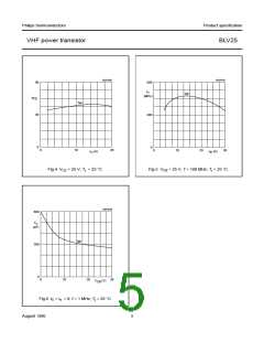
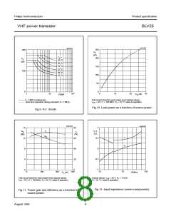
——— f > 1 MHz (continuous);
Test circuit tuned for each power level; typical values;
− − − − short time operation during mismatch (f > 1 MHz).
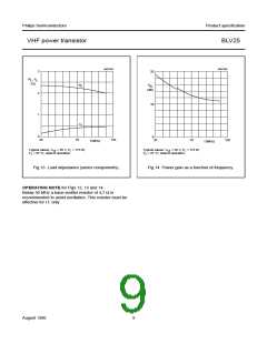
VCE = 28 V; f = 108 MHz; Th = 25 °C; class-B operation.
Fig.10 Load power as a function of source power.
Fig.9 R.F. SOAR.
MGP303
MGP304
1
16
80
handbook, halfpage
handbook, halfpage
r , x
η
G
p
(dB)
i
i
η
(%)
(Ω)
G
p
r
i
0.5
12
60
x
i
0
−0.5
−1
8
4
40
20
0
0
0
20
70
120
100
200
300
f (MHz)
P
(W)
L
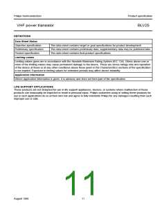
Test circuit tuned for each power level; typical values;
Typical values; VCE = 28 V; PL = 175 W;
VCE = 28 V; f = 108 MHz; Th = 25 °C; class-B operation.
Th = 25 °C; class-B operation.
Fig.12 Input impedance (series components).
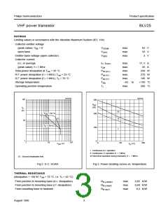
Fig.11 Power gain and efficiency as a function of
source power.
August 1986
8

 NXP [ NXP ]