Philips Semiconductors
Product specification
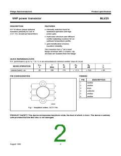
VHF power transistor
BLV25
RATINGS
Limiting values in accordance with the Absolute Maximum System (IEC 134)
Collector-emitter voltage
(peak value); VBE = 0
VCESM
max.
max.
max.
65 V
33 V
4 V
open base
VCEO
VEBO
Emitter-base voltage (open collector)
Collector current
d.c. or average
IC; IC(AV)
ICM
max.
max.
max.
max.
max.
17, 5 A
35 A
(peak value); f > 1 MHz
Total power dissipation at Tmb = 25 °C
R.F. power dissipation (f > 1 MHz); Tmb = 25 °C
R.F. power dissipation (f > 1 MHz); Th = 70 °C
Storage temperature
Ptot (d.c.)
Ptot (r.f.)
Ptot (r.f.)
Tstg
220 W
270 W
146 W
−65 to
+150 °C
200 °C
Operating junction temperature
Tj
max.
MGP294
MGP295
2
10
300
handbook, halfpage
handbook, halfpage
P
tot
(W)
I
C
(A)
ΙΙΙ
ΙΙ
T
T
= 25 °C
200
mb
(1)
10
= 70 °C
h
100
Ι
1
0
0
2
1
10
10
50
100
V
(V)
T
(°C)
CE
h
I
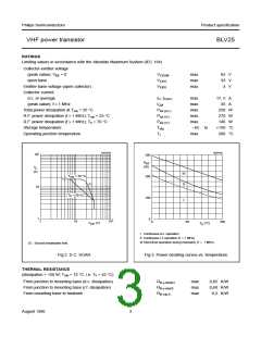
Continuous d.c. operation
II Continuous r.f. operation (f > 1 MHz)
III Short-time operation during mismatch; (f > 1 MHz).
(1) Second breakdown limit.
Fig.2 D.C. SOAR.
Fig.3 Power derating curves vs. temperature.
THERMAL RESISTANCE
(dissipation = 150 W; Tmb = 72 °C, i.e. Th = 42 °C)
From junction to mounting base (d.c. dissipation)
From junction to mounting base (r.f. dissipation)
From mounting base to heatsink
Rth j-mb(dc)
Rth j-mb(rf)
Rth mb-h
max
max
max
0,85 K/W
0,60 K/W
0,2 K/W
August 1986
3

 NXP [ NXP ]