NCP5316
If C
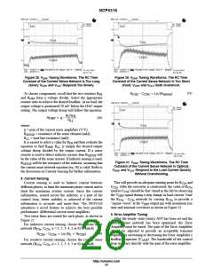
is too large, the loop gain/bandwidth will be low,
AMP
the COMP pin will slew too slowly and the output voltage
will overshoot as shown in Figure 32. On the other hand, if
C
AMP
is too small, the loop gain/bandwidth will be high, the
COMP pin will slew very quickly and overshoot will occur.
Integrator “wind up” is the cause of the overshoot. In this
case, the output voltage will transition more slowly because
COMP spikes upward as shown in Figure 33. Too much loop
gain/bandwidth increases the risk of instability. In general,
one should use the lowest loop gain/bandwidth possible to
achieve acceptable transient response. This will insure good
stability. If C
is optimal, the COMP pin will slew
AMP
quickly but not overshoot and the output voltage will
monotonically settle as shown in Figure 35.
After the control loop is tuned to provide an acceptable
transient response, the steady−state voltage ripple on the
COMP pin should be examined. When the converter is
operating at full steady−state load, the peak−to−peak voltage
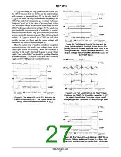
Figure 33. The Value of CAMP Is Too Low and the
Loop Gain/Bandwidth Too High. COMP Moves Too
Quickly, Which Is Evident from the Small Spike in Its
Voltage When the Load Is Applied or Removed. The
Output Voltage Transitions More Slowly Because of
the COMP Spike.
ripple (V ) on the COMP pin should be less than 20 mV
PP
PP
as shown in Figure 34. Less than 10 mV is ideal. Excessive
PP
ripple on the COMP pin will contribute to jitter.
Figure 34. At Full−Load the Peak−to−Peak Voltage
Ripple on the COMP Pin Should Be Less than 20 mV
for a Well−Tuned/Stable Controller. Higher COMP
Voltage Ripple Will Contribute to Output Voltage Jitter.
Figure 32. The Value of CAMP Is Too High and the
Loop Gain/Bandwidth Too Low. COMP Slews Too
Slowly Which Results in Overshoot in VOUT
.
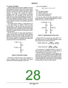
Figure 35. The Value of CAMP Is Optimal. COMP Slews
Quickly Without Spiking or Ringing. VOUT Does Not
Overshoot and Monotonically Settles to Its Final Value.
http://onsemi.com
27

 ONSEMI [ ONSEMI ]