NCP5316
10. Current Limit Setting
V
IO
can be calculated as
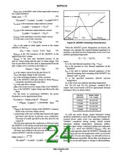
When the output of the current sense amplifier (COx in the
V
+ n @ I @ R @ g @ 3.3
F L L
IO
block diagram) exceeds the voltage on the I
will latch off. For inductive sensing, the I
pin, the part
pin voltage
LIM
where:
= the number of phases;
I = inductor current (A);
R = sense element resistance (W);
g = current sense to IO pin gain.
LIM
n
F
should be set based on the inductor’s maximum resistance
(R ). The design must consider the inductor’s
L
LMAX
L
resistance increase due to current heating and ambient
temperature rise. Also, depending on the current sense
points, the circuit board may add additional resistance. In
general, the temperature coefficient of copper is +0.39% per
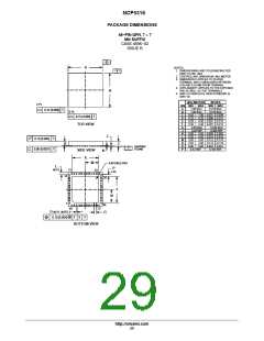
The user may easily set the phase and module current
limits at this point. This limit is programmed by a resistor
°C. If using a current sense resistor (R ), the I
SENSE
pin
divider from V , as shown in Figure 37.
LIM
REF
voltage should be set based on the maximum value of the
sense resistor.
V
REF
Since under transient conditions, a single phase may see
a very high positive or negative current for mere
microseconds at a time, the user may set a limit to the
maximum phase current. The phase current limit prevents an
individual phase from conducting too much current in either
R1
R2
R3
R4
I
I
PLIM
LIM
the positive or negative direction. The IP
set this threshold.
pin is used to
LIM
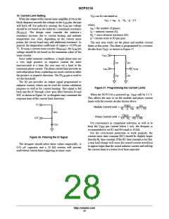
The IO pin provides an output signal proportional to
inductor current, which can be used for system validation
purposes as well as for current limiting. This signal is fed
back into the IC through a low−pass filter between IO and
IOF, as shown in Figure 36, so designers may customize the
response time of the current limit functions.
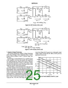
Figure 37. Programming the Current Limits
When the NCP5316 is powered up, V
will be 3.3 V.
REF
This allows the user to set the module and phase current
limits with the resistor divider shown above.
IO
V
R1
R1 ) R2
REF
Module Current Limit +
@
R @ g @ n
L
F
RIO
V
R3
R3 ) R4
REF
Phase Current Limit +
@
IOF
9.5 @ R
L
For convenience in component selection, as well as to
keep the V pin current below 1 mA, the designer is
CIO
REF
recommended to set R2 and R4 equal to 10 kW.
For the overcurrent protection to work properly, the
current sense time constant (RC) should be slightly larger
Figure 36. Filtering the IO Signal
than the R time constant. If the RC time constant is too fast,
L
a step load change will cause the sensed current waveform
to appear larger than the actual inductor current and will trip
the current limit at a lower level than expected.
The designer should select these values empirically. A
0.01 m F capacitor and a 20 kW resistor will prevent
inadvertent current limit triggering in many cases.
http://onsemi.com
28

 ONSEMI [ ONSEMI ]