NCP1631
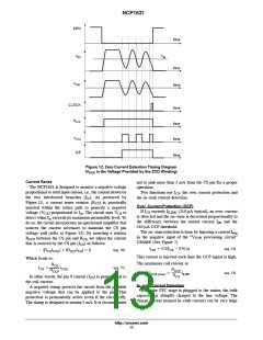
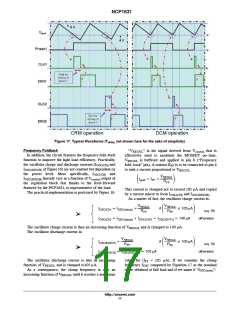
Figure 12. Zero Current Detection Timing Diagram
(VAUX is the Voltage Provided by the ZCD Winding)
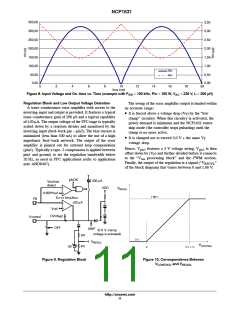
Current Sense
The NCP1631 is designed to monitor a negative voltage
proportional to total input current, i.e., the current drawn by
the two interleaved branches (I ). As portrayed by
Figure 13, a current sense resistor (R ) is practically
not to sink more than 5 mA from the CS pin for a proper
operation.
Two functions use I : the over current protection and
CS
the in−rush current detection.
in
CS
Over−Current Protection (OCP)
inserted within the return path to generate a negative
If I exceeds I
(210 mA typical), an over−current
CS
ILIM1
voltage (V ) proportional to I . The circuit uses V to
CS
in
CS
is detected and the on−time is decreased proportionally to
detect when I exceeds its maximum permissible level. To
in
the difference between the sensed current I and the
IN
do so, the circuit incorporates an operational amplifier that
sources the current necessary to maintain the CS pin
voltage null (refer to Figure 13). By inserting a resistor
210 mA OCP threshold.
The on−time reduction is done by injecting a current I
neg
in the negative input of the “V
OPAMP. (See Figure 7)
processing circuit”
TON
R
between the CS pin and R , we adjust the current
OCP
CS
that is sourced by the CS pin (I ) as follows:
CS
Ineg + 0.5(ICS * 210 m)
(eq. 12)
* [RCS COIL] ) [ROCPICS] + 0
I
(eq. 10)
(eq. 11)
This current is injected each time the OCP signal is high.
Which leads to:
The maximum coil current is:
RCS
ROCP
ICS
+
ICOIL
ROCP
RCS
ICOIL(max)
+
IILIM1
(eq. 13)
In other words, the pin 9 current (I ) is proportional to
CS
the coil current.
In−rush Current Detection
A negative clamp protects the circuit from the possible
negative voltage that can be applied to the pin. This
protection is permanently active (even if the circuit off).
The clamp is designed to sustain 5 mA. It is recommended
When the PFC stage is plugged to the mains, the bulk
capacitor is abruptly charged to the line voltage. The
charge current (named in−rush current) can be very huge
http://onsemi.com
13

 ONSEMI [ ONSEMI ]