NCP1396A, NCP1396B
450
350
250
150
50
16.0
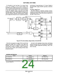
351 Volts
250 Volts
12.0
8.0
4.0
0
Vin
BO
60 m
20 m
100 m
140 m
180 m
time in seconds
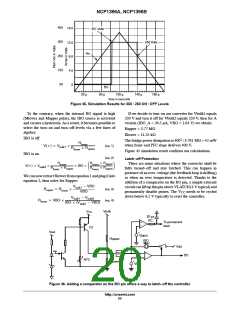
Figure 45. Simulation Results for 350 / 250 ON / OFF Levels
To the contrary, when the internal BO signal is high
(Mlower and Mupper pulse), the IBO source is activated
and creates a hysteresis. As a result, it becomes possible to
select the turn-on and turn-off levels via a few lines of
algebra:
If we decide to turn-on our converter for Vbulk1 equals
350 V and turn it off for Vbulk2 equals 250 V, then for A
version (IBO_A = 26.5 mA, VBO = 1.04 V) we obtain:
Rupper = 3.77 MΩ
Rlower = 11.25 kΩ
The bridge power dissipation is 4002 / 3.781 MΩ = 42 mW
IBO is off
Rlower
Rlower + Rupper
when front-end PFC stage delivers 400 V.
V(+) = Vbulk1
×
(eq. 1)
Figure 45 simulation result confirms our calculations.
IBO is on
(eq. 2)
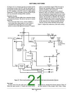
Latch--off Protection
R
× R
+ R
R
lower
There are some situations where the converter shall be
fully turned-off and stay latched. This can happen in
presence of an over-voltage (the feedback loop is drifting)
or when an over temperature is detected. Thanks to the
addition of a comparator on the BO pin, a simple external
circuit can lift up this pin above VLATCH(4 V typical)and
permanently disable pulses. The VCC needs to be cycled
down below 6.5 V typically to reset the controller.
upper
upper
lower
+ IBO ×
V(+) = V
×
bulk2
R
+ R
R
upper
lower
lower
We can now extract Rlower from equation1 andplug it into
equation 2, then solve for Rupper:
Vbulk1 − VBO
Rupper = Rlower
×
(eq. 3)
(eq. 4)
Vbulk
VBO
Vbulk1 − Vbulk2
IBO × (Vbulk1 − VBO)
Rlower = VBO ×
V
CC
20 ms
RC
+
--
To permanent
latch
Q1
Vout
+
Vlatch
Rupper
IBO
Vdd
BO
Rlower
+
--
BO
NTC
+
VBO
Figure 46. Adding a comparator on the BO pin offers a way to latch--off the controller
http://onsemi.com
20

 ONSEMI [ ONSEMI ]