NCP1396A, NCP1396B
V
CC(on)
V
CC(min)
Vcc from an auxiliary supply
SS
FB
T
SS
T
SS
Fault!
0.6 V
A&B
A
B
A
B
Timer
4 V
1 V
Slopes are similar
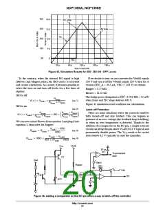
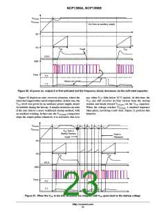
Figure 50. At power on, output A is first activated and the frequency slowly decreases via the soft--start capacitor
Figure 50 depicts an auto-recovery situation, where the
timerhastriggeredthe endof output pulses. Inthat case, the
VCC level was given by an auxiliary power supply, hence
its stability during the hiccup. A similar situation can arise
if the user selects a more traditional startup method, with
an auxiliary winding. In that case, the VCC(min) comparator
stops the output pulses whenever it is activated, that is to
say, when VCC falls below 10 V typical. At this time, the
VCC pin still receives its bias current from the startup
resistor and heads toward VCC(on) via the VCC capacitor.
When the voltage reaches VCC(on), a standard sequence
takes place, involving a soft-start. Figure 51 portrays this
behavior.
V
CC(on)
V
CC(min)
V
CC
from a
Startup Resistor
Fault is
Fault!
Released
SS
FB
T
SS
T
SS
0.6 V
A&B
A
B
A
B
Timer
4 V
1 V
Figure 51. When the V is too low, all pulses are stopped until V goes back to the startup voltage
CC
CC
http://onsemi.com
23

 ONSEMI [ ONSEMI ]