NCP1396A, NCP1396B
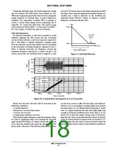
reaches the VtimerON level (4 V typical), then all pulses
/ Itimer otherwise the voltage on Ctimer will not reach the
turn-off voltage of 4 V.
are stopped. If the fault input signal is still present, then the
controller permanently stays off and the voltage on the
timer capacitor does not move (Itimer is on and the voltage
is clamped to 5 V). If the fault input signal is removed
(because pulses are off for instance), Itimer turns off and
the capacitor slowly discharges to ground via a resistor
installed in parallel with it. As a result, the designer can
easily determine the time during which the power supply
stays locked by playing on Rtimer. Now, when the timer
capacitor voltage reaches 1 V typical (VtimerOFF), the
comparatorinstructs the internal logic to issuespulses ason
a clean soft-start sequence (soft-start is activated). Please
note that the discharge resistor can not be lower than 4 V
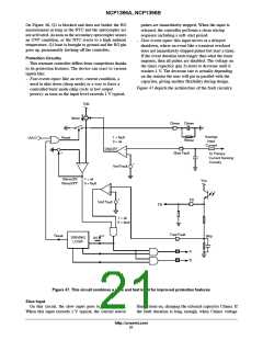
In both cases, when the fault is validated, both outputs
Mlower and Mupper are internally pulled down to ground.
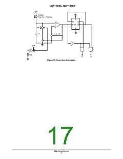
On Figure 46 example, a voltage proportional to primary
current, once averaged, gives an image of the input power
in case Vin is kept constant via a PFC circuit. If the output
loading increases above a certain level, the voltage on this
pin will pass the 1 V threshold and start the timer. If the
overload stays there, after a few tens of milli-seconds,
switching pulses will disappear and
a protective
auto-recovery cycle will take place. Adjusting the resistor
R in parallel with the timer capacitor will give the
flexibility to adjust the fault burst mode.
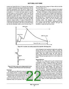
SMPS Stops
4 V
Fault is Gone
SMPS Re--starts
1 V
Reset at Re--start
Figure 48. A resistor can easily program the capacitor discharge time
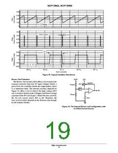
V
CC
can be designed to lose regulation in light load conditions,
forcing the FB level to increase. When it reaches the
programmed level, it triggers the fast fault input and stops
pulses. Then Vout slowly drops, the loop reacts by
decreasing the feedback level which, in turn, unlocks the
pulses, Vout goes up again and so on: we are in skip cycle
mode.
FB
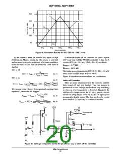
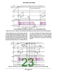
Startup Behavior
Fast Fault
When the VCC voltage grows-up, the internal current
consumption is kept to Istrup, allowing to crank-up the
converter via a resistor connected to the bulk capacitor.
When VCC reaches the VCC(on) level, output Mlower goes
high first and then output Mupper. This sequence will
always be the same whatever triggers the pulse delivery:
fault, OFFto ONetc Pulsingthe output Mlower highfirst
gives an immediate charge of the bootstrap capacitor.
Then, the rest of pulses follow, delivered at the highest
switching value, set by the resistor on pin 2. The soft-start
capacitor ensures a smooth frequency decrease to eitherthe
programmed minimum value (in case of fault) or to a value
corresponding to the operating point if the feedback loop
closes first. Figure 50 shows typical signals evolution at
power on.
Figure 49. Skip cycle can be implemented via two
resistors on the FB pin to the Fast fault input
Fast Input
The fast input is not affected bya delayedaction. Assoon
as its voltage exceeds 1 V typical, all pulses are off and
maintained off as long as the fault is present. When the pin
isreleased, pulsescome backand the soft-start isactivated.
Thanks to the low activation level of 1 V, this pin can
observe the feedback pin via a resistive divided and thus
implement skip cycle operation. The resonant converter
http://onsemi.com
22

 ONSEMI [ ONSEMI ]