NCP1396A, NCP1396B
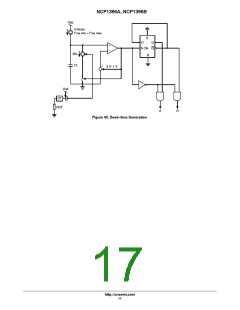
On Figure 46, Q1 is blocked and does not bother the BO
pulses are immediately stopped. When the input is
released, the controller performs a clean startup
sequence including a soft-start period.
measurement as long as the NTC and the optocoupler are
not activated. As soon as the secondary optocoupler senses
an OVP condition, or the NTC reacts to a high ambient
temperature, Q1 base is brought to ground and the BO pin
goes up, permanently latching off the controller.
- Slow events input: this input serves as a delayed
shutdown, where an event like a transient overload
does not immediately stopped pulses but start a timer.
If the event duration lasts longer than what the timer
imposes, then all pulses are disabled. The voltage on
the timer capacitor (pin 3) starts to decrease until it
reaches 1 V. The decrease rate is actually depending
on the resistor the user will put in parallel with the
capacitor, giving another flexibility during design.
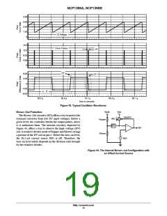
Protection Circuitry
This resonant controller differs from competitors thanks
to its protection features. The device can react to various
inputs like:
- Fast events input: like an over-current condition, a
need to shut down (sleep mode) or a way to force a
controlled burst mode (skip cycle at low output
power): as soon as the input level exceeds 1 V typical,
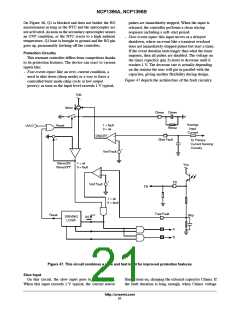
Figure 47 depicts the architecture of the fault circuitry.
Vdd
Itimer
Ctimer Ctimer
Average
Input
Current
1 = fault
0 = ok
Reset
UVLO
Rtimer
+
ON/OFF
+
-
Slow Fault
To Primary
Current Sensing
Circuitry
+
+
-
Vref Fault
VtimerON
VtimerOFF
1 = ok
0 = fault
V
CC
-
+
+
FB
Vref Fault
FB
1 = ok
0 = fault
Fast Fault
Reset
Skip
DRIVING
LOGIC
SS
A
B
A
B
Figure 47. This circuit combines a slow and fast input for improved protection features
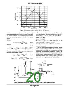
Slow Input
On this circuit, the slow input goes to a comparator.
When this input exceeds 1 V typical, the current source
Itimer turns on, charging the external capacitor Ctimer. If
the fault duration is long enough, when Ctimer voltage
http://onsemi.com
21

 ONSEMI [ ONSEMI ]