NCL37733
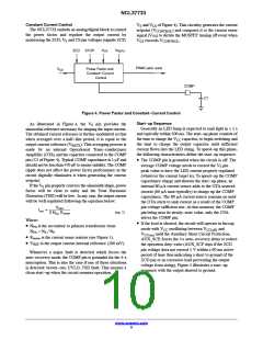
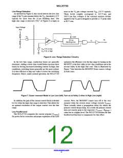
Figure 5. Start−up Sequence in a Load Short−circuit Situation
Zero Crossing Detection Block
operation recovery after a fault), the ZCD blanking time is
(3 ms typically) and keeps this value until the
The CS/ZCD pin detects when the drain−source voltage
of the power MOSFET reaches a valley by crossing down
the 55 mV internal threshold and initiates a new DRV pulse
at that moment. At startup and in overload conditions, the
ZCD comparator may not be able to detect the
demagnetization signal. To allow a new DRV pulse to occur,
the NCL37733 features a watchdog timer which initiates a
DRV pulse if the CS/ZCD pin voltage does not trig the ZCD
comparator for the watchdog time. The watchdog duration
is typically 55 ms at low line. It increases to 62 ms when the
line range is detected (see next section).
t
ZCD(blank2)
ZCD signal is high enough to be detected by the ZCD
comparator (higher than V , 90 mV typically). At
ZCD(rising)
that moment, the ZCD blanking time recovers its nominal
level (t =1.5 ms, typically).
ZCD(blank1)
If the ZCD pin or the auxiliary winding happen to be
shorted, the watchdog function would normally make the
controller keep switching and hence lead to improper LED
current regulation. The “AUX_SCP” protection prevents
such a stressful operation: a timer starts counting which is
only reset when the ZCD voltage exceeds the V
ZCD(short)
As detailed in next section, the NCL37733 operates in QR
mode at low line and at valley 2 in high−line conditions. If
the auxiliary winding free oscillations are extremely
damped, the ZCD comparator may not be able to detect the
second valley as necessary at high line. To overcome this
high−line situation, the NCL37733 features a time−out
circuit to initiate a DRV pulse if once the demagnetization
is detected, the CS/ZCD pin voltage stays below the ZCD
comparator internal threshold for about 7.3 ms. Hence, the
time−out acts as a substitute clock for valley−2 detection.
threshold (1 V typically). If this timer reaches 90 ms (no
ZCD voltage pulse having exceeded V for this time
period), the controller detects a fault and stops operation for
4 seconds.
ZCD(short)
The CS/ZCD pin is grounded for 325 ns (time T of the
1
parametric table) when the drive turns low. This prevents a
possible CS residual voltage to be taken into account by the
ZCD comparator, which could otherwise occur in particular
if a filtering capacitor was added to the pin. Similarly, the
CS/ZCD pin is “reset” when the drive turns high. Practically,
the pin is grounded for the 175 ns t
time (Leading Edge
BCS
In other words:
Blanking Duration for V ) to in this case, avoid that a
CS(stop)
• The timeout timer initiates a DRV pulse at high line if
valley 1 is detected but valley 2 cannot be detected.
• The watchdog timer prevents the circuit from keeping
permanently off if no demagnetization signal can be
detected (e.g. at startup).
V
AUX
remaining voltage alters the current sense block
operation.
For an optimal operation, the maximum ZCD level
should be maintained below 5 V to stay safely below the
built in clamping voltage of the pin.
Whenever the controller enters operation (cold startup,
restart after a failure to startup at the first attempt or
www.onsemi.com
10

 ONSEMI [ ONSEMI ]