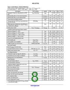
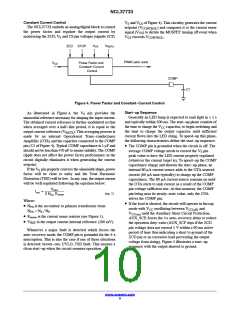
NCL37733
S
DRV
Q
Q
CS
R
LEB1
+
PWMreset
Ipkmax
Vcontrol / 4
−
+
STOP
−
UVLO
BONOK
TSD
VILIMIT
OVP2
LEB2
+
WOD_SCP
4−pulse
counter
−
S
R
OFF
AUX_SCP
VCC(ovp)
Q
Q
VCS(stop)
4−s auto−recovery timer
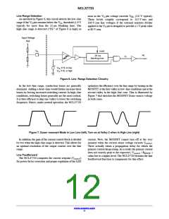
Figure 9. Winding Short Circuit Protection, Max. Peak Current Limit Circuits
• V Over Voltage Protection
• Brown−Out Protection
CC
The circuit stops generating pulses if V exceeds
The NCL37733 prevents operation when the line
voltage is too low for proper operation. As sketched in
Figure 10, the circuit detects a brown−out situation
CC
V
and enters auto−recovery mode. This feature
CC(OVP)
protects the circuit if the output LED string happens to
open or is disconnected.
(BONOK is high) if the V pin remains below the
S
V
threshold (0.9 V typical) for more than the
• Programmable Over Voltage Protection (OVP2)
BO(off)
25 ms blanking time. In this case, the controller stops
operating. Operation resumes as soon as the V pin
voltage exceeds V
higher than V
overrides the V normal sequence (no need for V
cycling down below V
immediately reduces to I
charges up to V
operating.
The ZCD signal is compared to an internal 4.5 V
S
threshold. If V
exceeds this threshold for more than
ZCD
(1.0 V typical) and V is
BO(on)
CC
1 ms (after the ZCD blanking time), an OVP event is
detected. If this happens for 4 consecutive switching
cycles, an OVP fault is detected and the system enters
auto−recovery mode.
. To ease recovery, the circuit
CC(on)
CC
CC
). Instead, its consumption
CC(off)
so that V rapidly
CC(start)
CC
• Cycle−by−Cycle Current Limit
. Once done, the circuit re−starts
CC(on)
When the current sense voltage exceeds the internal
threshold V , the MOSFET is turned off for the rest
ILIM
of the switching cycle.
Input Voltage
Rail
V
S
reset
25 ms
+
BONOK
blanking time
−
V
V
if BONOK is high
if BONOK is low
BO(on)
BO(off)
Figure 10. Brown−out Protection Circuit
www.onsemi.com
13

 ONSEMI [ ONSEMI ]