CJ2M-CPU3@/-CPU1@/-MD21@
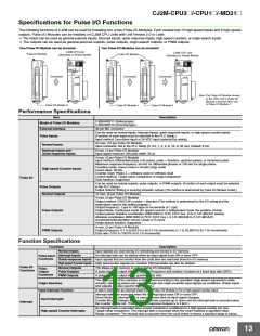
Specifications of Pulse Input Functions
Interrupt Inputs
Item
Number of interrupt inputs
Allocated bit
Direct Mode
Counter Mode
Max. 8 inputs
CIO 2960 and CIO 2962, bits 00 to 03
ON-to-OFF or OFF-to-ON transitions
140 to 147 (fixed)
Interrupt detection method
Interrupt task numbers
Incrimenting or decrementing
(Set with the MSKS(690) instruction.)
Counting method
---
0001 to FFFF hex (16 bits)
(Set in A532 to A535 and A544 to A547.)
Counting range
---
---
---
Response frequency
Single-phase: 3 kHz x 8 inputs
Storage locations for PVs for interrupt inputs
in Counter Mode
A536 to A539 and A548 to A551
Quick-response inputs
Item
Specifications
Number of Quick-response inputs
Max. 8 inputs
Signals that are shorter than the cycle time are latched for one PLC cycle, so they can be detected in the PLC program.
Minimum detectable pulse width is 30 μs.
Quick-response inputs
High-speed Counter Inputs
Item
Description
Number of High-speed Counter Inputs
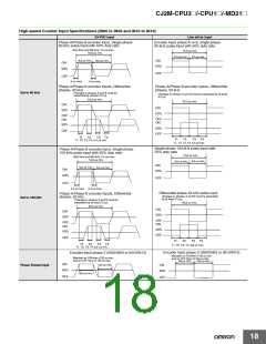
Pulse input method (counting mode)
Max. 4 inputs
Incremental pulse inputs
Differential phase input (4×) Up/down inputs
Pulse + direction inputs
Increment pulse
Phase A
Phase B
Phase Z
Up pulse
Down pulse
Reset
Pulse
Input signals
---
---
Direction
Reset
Frequency and number of high-speed
counters
100 kHz, 2 inputs × 2 I/O
Modules
50 kHz, 2 inputs × 2 I/O
Modules
100 kHz, 2 inputs
× 2 I/O Modules
100 kHz, 2 inputs
× 2 I/O Modules
Counting mode
Linear mode or ring mode
Linear mode:
8000 0000 to 7FFF FFFF hex
0000 0000 to FFFF FFFF hex (for increment pulse)
Count value
Ring mode:
0000 0000 to Max. ring value
High-speed counter 0: A271 (upper 4 digits) and A270 (lower 4 digits)
High-speed counter 1: A273 (upper 4 digits) and A272 (lower 4 digits)
High-speed counter 2: A317 (upper 4 digits) and A316 (lower 4 digits)
High-speed counter 3: A319 (upper 4 digits) and A318 (lower 4 digits)
Refreshed during overseeing processing. Use PRV(881) to read the most recent PVs.
High-speed counter PV storage locations
Data format: 8 digit hexadecimal
• Linear mode:
8000 0000 to 7FFF FFFF hex
0000 0000 to FFFF FFFF hex (for increment pulse)
0000 0000 to Max. ring value
• Ring mode:
Target value comparison Up to 48 target values and corresponding interrupt task numbers can be registered.
Control method
Up to 8 or up to 32 ranges can be registered, with a separate upper limit, lower limit, and interrupt task number for each
Range Comparison
range.
• Phase-Z + Software reset
The counter is reset when the phase-Z input goes ON while the Reset Bit (A531.00 to A531.03) is ON.
Counter reset method
• Software reset
The counter is reset when the Reset Bit (A531.00 to A531.03) is turned ON.
Operation can be set to stop or continue the comparison operation when the high-speed counter is reset.
15

 OMRON [ OMRON ELECTRONICS LLC ]