CJ2M-CPU3@/-CPU1@/-MD21@
Specifications for Pulse I/O Functions
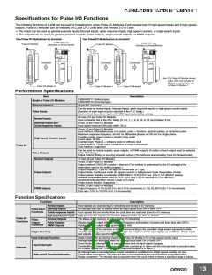
The following functions of CJ2M can be used by installing one or two Pulse I/O Modules. Each module has 10 high-speed inputs and 6 high-speed
outputs. Pulse I/O Modules can be installed on CJ2M CPU Units with Unit Version 2.0 or Later.
•
The inputs can be used as general-purpose inputs, interrupt inputs, quick-response inputs, high-speed counters, or origin search inputs.
• The outputs can be used as general-purpose outputs, pulse outputs, origin search outputs, or PWM outputs.
One Pulse I/O Module can be mounted
CJ2M CPU Unit
(Standard or Simple Model)
Two Pulse I/O Modules can be mounted
CJ2M CPU Unit
(Standard or Simple Model)
Pulse I/O Module
Pulse I/O Module
Connected
Connected
Connected
Note: The Pulse I/O Module closest
to the CPU Unit is Pulse I/O
Module 0 and the other one
is Pulse I/O Module 1.
Pulse I/O Module 0
Pulse I/O Module 1
Pulse I/O Module 0
Performance Specifications
Item
Description
CJ2M-MD211 (Sinking-type)
CJ2M-MD212 (Sourcing-type )
Model of Pulse I/O Modules
External Interface
40-pin MIL connector
Can be used as normal inputs, interrupt inputs, quick-response inputs, or high-speed counter inputs.
(Function of each input must be selected in the PLC Setup.)
Input method: Line-driver input or 24-VDC input (selected by wiring)
Pulse Inputs
20 max. (10 per Pulse I/O Module)
Input constants: Set in the PLC Setup (0, 0.5, 1, 2, 4, 8, 16, or 32 ms). Default: 8 ms
Normal Inputs
Interrupt Inputs and
Quick-response Inputs
8 max. (4 per Pulse I/O Module)
Input signal minimum ON pulse width: 30 μs
4 max. (2 per Pulse I/O Module)
Input method: Differential-phase (×4) pulses, pulse + direction, up/down pulses, or increment pulse
Maximum response frequency: 50 kHz for differential phases or 100 kHz for single phase
Counting mode: Linear mode or circular (ring) mode
Count value: 32 bits
Counter reset: Phase Z + software reset or software reset
Control method: Target-value comparison or range comparison
Gate function: Supported
High-speed Counter Inputs
Pulse I/O
Can be used as normal outputs, pulse outputs, or PWM outputs. (Function of each output must be selected
in the PLC Setup.)
Output method: Sinking or sourcing transistor outputs (The method is determined by Pulse I/O Module model.)
Pulse Outputs
Normal Outputs
12 max. (6 per Pulse I/O Module)
4 max. (2 per Pulse I/O Module)
Output method: CW/CCW or pulse + direction (The method is determined by the I/O wiring and the
instructions used in the ladder program.)
Output frequency: 1 pps to 100 kpps (in increments of 1 pps)
Output Mode: Continuous mode (for speed control) or independent mode (for position control)
Output pulses: Relative coordinates: 0000 0000 to 7FFF FFFF hex (0 to 2,147,483,647 pulses)
Absolute coordinates: 8000 0000 to 7FFF FFFF hex (−2,147,483,648 to 2,147,483,647)
Acceleration/deceleration curves: Linear or S-curve
Pulse Outputs
Origin search function: Supported
4 max. (2 per Pulse I/O Module)
Output frequency: 0.1 to 6,553.5 Hz (in 0.1-Hz increments) or 1 to 32,800 Hz (in 1-Hz increments)
Duty ratio: 0.0% to 100.0% (in 0.1% increments)
PWM Outputs
Function Specifications
Functions
Description
Normal Inputs
Input signals are read during I/O refreshing and stored in I/O memory.
An interrupt task can be started when an input signal turns ON or turns OFF.
Interrupt Inputs
Pulse Input
Functions
Quick-response Inputs Input signals that are shorter than the cycle time are read and stored in I/O memory.
High-speed Counter Inputs High-speed pulse signals are counted. Interrupt tasks can also be started.
Pulse I/O
Functions
Normal Outputs
Pulse Outputs
PWM Outputs
The status of I/O memory is output during I/O refreshing.
Pulse
Output
Functions
A pulse signal is output with the specified frequency and number of pulses at a fixed duty ratio (50%).
A pulse signal is output at the specified duty ratio.
The origin point of the machine is determined according to the specified origin search parameters while
actually outputting pulses and using the origin and origin proximity input signals as conditions. (Pulse inputs
and outputs are also used for this function.)
Origin Searches
Input Interrupt Function
A task is started for an interrupt input from a Pulse I/O Module or for a high-speed counter input.
Interrupt tasks are executed when the interrupt input turns ON or turns OFF.
Direct Mode: An interrupt task is executed each time an input signal changes.
Counter Mode: Changes in the input signal are counted up or down and the interrupt task is executed when
the counter counts out. (The maximum response frequency is 3 kHz.)
Input Interrupts
Interrupt
An interrupt task is executed when preset comparison conditions for a high-speed counter are met.
Target-value comparison: The interrupt task is executed when the count matches a specified value.
Range comparison: The interrupt task is executed when the count enters or leaves a specified range of values.
High-speed Counter Interrupts
13

 OMRON [ OMRON ELECTRONICS LLC ]