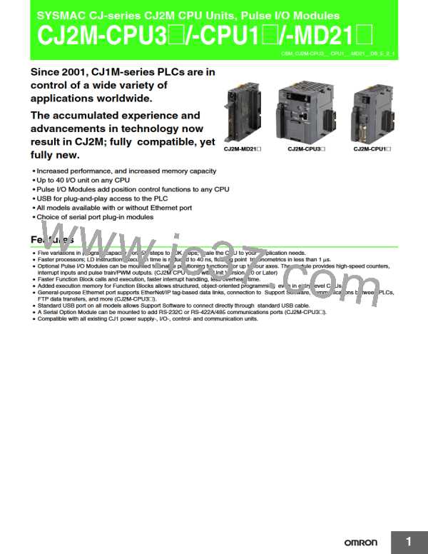
CJ2M-CPU3@/-CPU1@/-MD21@
Function
Description
Communications
Peripheral (USB)
Port
−
Bus for communications with various kinds of Support Software running on a personal
computer. High-speed communications are supported.
Peripheral Bus
Serial Port (Option) *11
Application is possible when a Serial Communications Option Board is mounted.
Host Link commands or FINS commands placed between Host Link headers and terminators
can be sent from a host computer or PT to read/write I/O memory, read/control the operating
mode, and perform other operations for PLC.
Host Link (SYSWAY) Communications
I/O instructions for communications ports (such as TXD/RXD instructions) can be used for
data transfer with peripheral devices such as bar code readers and printers.
No-protocol Communications
NT Link Communications
I/O memory in the PLC can be allocated and directly linked to various PT functions, including
status control areas, status notification areas, touch switches, lamps, memory tables, and
other objects.
Bus for communications with various kinds of Support Software running on a personal
computer. High-speed communications are supported.
Peripheral Bus
Serial Gateway
Serial PLC Links
This gateway enables receiving and automatically converting FINS to the CompoWay/F.
Data is exchanged between CPU Units using serial ports without communications
programming. PTs set to the 1:N NT Link protocol can be included in the network.
100Base-TX/10Base-T
Protocols: TCP/IP, UDP, ARP, ICMP (ping only), BOOTP
Applications: FINS, CIP, SNTP, DNS (Client), FTP (Server)
EtherNet/IP Port *12
CIP
Tag Data Links
Programless cyclic data exchanges with the devices on the EtherNet/IP network.
Any CIP commands can be received from the devices on the EtherNet/IP network.
Communications
Service
Message Communications
FINS
Communications Message Communications
Service
Any FINS commands can be transferred with the devices on the EtherNet/IP network.
Tasks can be executed at a specified interval (minimum of 0.2 ms, Unit: 0.1 ms).
Scheduled Interrupts
When MSKS(690) is executed, the internal timer is restarted and the time to first interrupt is
set to a fixed value.
Resetting and restarting with MSKS(690)
Reading present value of internal timer with
MSKS(690)
MSKS(690) can be used to read the time that has elapsed until the schedule interrupt is started
or since the previous scheduled interrupt.
Interrupt
Power OFF Interrupts
I/O Interrupt Tasks
A task can be executed when CPU Unit's power turns OFF.
A task can be executed when an input signal is input to an Interrupt Input Unit.
A task can be executed when interrupts are requested from a Special I/O Unit or a CPU Bus Unit.
External Interrupt Tasks
Clock data is stored in memory.
Accuracy (Accuracy depends on the temperature.)
Ambient temperature of 55°C : −3.5 to +0.5 min error per month
Ambient temperature of 25°C : −1.5 to +1.5 min error per month
Ambient temperature of 0°C : −3 to +1 min error per month
Clock Function
Operation Start Time Storage
Operation Stop Time Storage
The time when operating mode was last changed to RUN mode or MONITOR mode is stored.
The last time a fatal error occurred or the last time the operating mode was changed to
PROGRAM mode is stored.
Clock
Startup Time Storage
The time when the power was turned ON is stored.
Power Interruption Time Storage
Total Power ON Time Calculation
Power ON Clock Data Storage
User Program Overwritten Time Storage
Parameter Date Storage
The time when the power is turned OFF is stored.
The total time that the PLC has been ON is stored in increments of 10 hours.
A history of the times when the power was turned ON is stored.
The time that the user program was last overwritten is stored.
The time when the Parameter Area was overwritten is stored.
Holding Area data, DM Area data, EM Area data, Counter Completion Flags, and counter
present values are held even when power is turned OFF. CIO Area, Work Area, some Auxiliary
Area data, and Timer Completion Flags, timer present values, index registers, and data
registers can be protected by turning ON the IOM Hold Bit in the Auxiliary Area, and by also
setting the IOM Hold Bit to “Hold” in the PLC Setup.
Memory Protection
Power
Supply
Management
The detection time for power interruptions can be set.
AC power supply: 10 to 25 ms (variable)
DC power supply: 2 to 5 ms (CJ1W-PD022) or 2 to 20 ms (CJ1W-PD025)
Power OFF Detection Time Setting
The detection of power interruptions can be delayed: 0 to 10 ms
(Not supported by the CJ1W-PD022.)
Power OFF Detection Delay Time
Number of Power Interruptions Counter
The number of times power has been interrupted is counted.
*12.A Serial Option Board is required to use a serial port for the CJ2M-CPU3@ CJ2M CPU Unit.
*13.Supported only by the CJ2M-CPU3@.
10

 OMRON [ OMRON ELECTRONICS LLC ]