Functional Description (Continued)
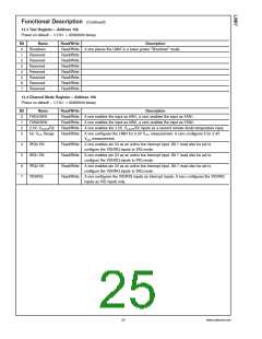
13.5 Configuration Register 1—Address 40h
<
>
Power on default – 7:0 = 00001000 binary
Bit
Name
Read/Write
Description
0
Start
Read/Write A one enables startup of monitoring operations, a zero puts the part in standby mode.
Note: The outputs of Interrupt pins will not be cleared if the user writes a zero to this
location after an interrupt has occurred, unlike the “INT_Clear” bit.
At start up, limit checking functions and scanning begin. Note, all limits should be set in
the Value RAM before setting this bit HIGH.
#
#
Read/Write A one enables the INT Interrupt output.
1
2
INT Enable
THERM#
Enable
#
Read/Write A one enables the THERM Interrupt output.
#
3
4
INT#_Clear
Read/Write A one disables the INT output without affecting the contents of Interrupt Status
Registers. The device will stop monitoring. It will resume upon clearing of this bit.
#
#
RESET
Read/Write A one outputs a 20 ms minimum active low reset signal at RESET . This bit is cleared
once the pulse has gone inactive.
Read/Write
5
6
Reserved
#
THERM#_Clear
Read/Write A one disables the THERM output without affecting the contents of Interrupt Status
Registers.
7
INITIALIZATION
Read/Write A one restores power on default values to the Configuration Register, Interrupt Status
Registers, Interrupt Mask Registers, CI Clear Register, VID/Fan Divisor Register, VID4,
Temperature Configuration Register, and the Extended Mode Registers. This bit clears
itself since the power on default is zero.
13.6 Interrupt Status Register 1—Address 41h
<
>
Power on default – 7:0 = 0000 0000 binary
Bit
0
Name
+2.5Vin
Vccp1
Read/Write
Read Only
Read Only
Read Only
Read Only
Read Only
Read Only
Read Only
Description
A one indicates a High or Low limit has been exceeded.
A one indicates a High or Low limit has been exceeded.
A one indicates a High or Low limit has been exceeded.
A one indicates a High or Low limit has been exceeded.
A one indicates a High or Low limit has been exceeded.
A one indicates a High or Low limit has been exceeded.
A one indicates the fan count limit has been exceeded or an AIN1 High or Low limit has
been exceeded.
1
2
Vcc
3
+5Vin
4
Int. Temp.
Ext. Temp.
FAN1/AIN1
5
6
7
FAN2/AIN2
Read Only
A one indicates the fan count limit has been exceeded or an AIN2 High or Low limit has
been exceeded.
www.national.com
26

 NSC [ National Semiconductor ]