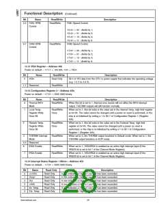
Functional Description (Continued)
Bit
Name
Read Only
Description
A one indicates the fan count limit has been exceeded or an AIN1 High or Low limit has
been exceeded.
6
FAN1/AIN1
Read Only
7
FAN2/AIN2
Read Only
A one indicates the fan count limit has been exceeded or an AIN2 High or Low limit has
been exceeded.
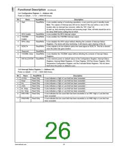
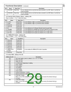
13.16 Interrupt Status Register 2 Mirror—Address 4Dh
<
>
Power on default – 7:0 = 0000 0000 binary
Bit
0
Name
+12Vin
Read Only
Read Only
Read Only
Read Only
Read Only
Read Only
Read Only
Read Only
Read Only
Description
A one indicates a High or Low limit has been exceeded.
A one indicates a High or Low limit has been exceeded.
1
Vccp2
2
Reserved
Reserved
CI
3
4
A one indicates the CI (Chassis Intrusion) input has gone high.
A one indicates the THERM# input has been pulled low by external circuitry.
A one indicates the D1 inputs are shorted to Vcc or open circuit.
A one indicates the D2 inputs are shorted to Vcc or open circuit.
5
THERM#
D1 Fault
D2 Fault
6
7
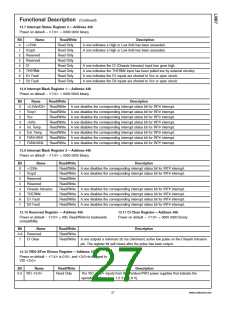
13.17 SMBALERT# Enable—Address 80h
<
>
Power on default – 7:0 = 0010 0000 binary
Bit
0
Name
Reserved
Read/Write
Read Only
Read Only
Read Only
Read Only
Read Only
Read Only
Read/Write
Description
1
Reserved
Reserved
Reserved
Reserved
Reserved
SMBALERT#
Enable
2
3
4
5
6
A one enables the SMBALERT# mode of operation.
7
Reserved
Read Only
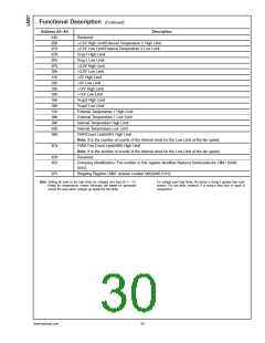
13.18 Value RAM—Address 19h–3Fh
Address A6–A0
Description
<
>
19h
1Ah
1Bh
20h
21h
22h
23h
24h
25h
26h
27h
28h
DAC data register; power on default 7:0 =1111 1111 binary
AIN1 Low Limit
AIN2 Low Limit
+2.5V/External Temperature 2 reading
Vccp1 reading
+Vcc reading
+5V reading
+12V reading
Vccp2 reading
External Temperature 1 reading
Internal Temperature reading
FAN1/AIN1 reading
Note: For the FAN reading, this location stores the number of counts of the internal clock per
revolution.
29h
FAN2/AIN2 reading
Note: For the FAN reading, this location stores the number of counts of the internal clock per
revolution.
29
www.national.com

 NSC [ National Semiconductor ]