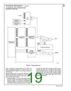
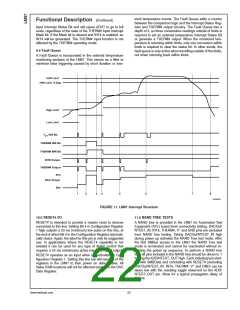
sient temperature events. The Fault Queue adds a counter
between the comparison logic and the Interrupt Status Reg-
ister and THERM# output circuitry. The Fault Queue has a
depth of 3, so three consecutive readings outside of limits is
required to set an external temperature Interrupt Status Bit
or generate a THERM# output. When the monitored tem-
perature is returning within limits, only one conversion within
limits is required to clear the status bit. In other words, the
fault queue is only active when travelling outside of the limits,
not when returning back within limits.
Functional Description (Continued)
input Interrupt Status Bit and will cause AOUT to go to full
scale, regardless of the state of the THERM# Input Interrupt
Mask bit. If the Mask bit is cleared and INT# is enabled, an
INT# will be generated. The THERM# input function is not
affected by the THERM# operating mode.
9.4 Fault Queue
A Fault Queue is incorporated in the external temperature
monitoring sections of the LM87. This serves as a filter to
minimize false triggering caused by short duration or tran-
10099532
FIGURE 11. LM87 Interrupt Structure
#
10.0 RESET I/O
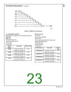
11.0 NAND TREE TESTS
#
RESET is intended to provide a master reset to devices
A NAND tree is provided in the LM87 for Automated Test
Equipment (ATE) board level connectivity testing. DACOut/
connected to this line. Setting Bit 4 in Configuration Register
1 high outputs a 20 ms (minimum) low pulse on this line, at
the end of which Bit 4 in the Configuration Register automati-
cally clears. Again, the label for this pin is only its suggested
use. In applications where the RESET capability is not
needed it can be used for any type of digital control that
requires a 20 ms (mimimum) active low, open-drain output.
NTEST_IN, INT#, THERM , V+ and GND pins are excluded
#
from NAND tree testing. Taking DACOut/NTEST_IN high
during power up activates the NAND Tree test mode. After
the first SMBus access to the LM87 the NAND Tree test
mode is terminated and cannot be reactivated without re-
peating the power up sequence. To perform a NAND tree
test, all pins included in the NAND tree should be driven to 1
forcing the ADD/NTEST_OUT high. Each individual pin start-
#
#
RESET operates as an input when not activated by Con-
figuration Register 1. Setting this line low will reset all of the
registers in the LM87 to their power on default state. All
Value RAM locations will not be affected except for the DAC
Data Register.
ing with SMBData and concluding with RESET# (excluding
+
#
DACOut/NTEST_IN, INT#, THERM , V and GND) can be
taken low with the resulting toggle observed on the ADD/
NTEST_OUT pin. Allow for a typical propagation delay of
500 ns.
www.national.com
22

 NSC [ National Semiconductor ]