Functional Description (Continued)
Bit
Name
Read/Write
Description
4-5 FAN1 RPM
Control
Read/Write
FAN1 Speed Control.
<
<
<
<
>
5:4 = 00 - divide by 1;
>
5:4 = 01 - divide by 2;
>
5:4 = 10 - divide by 4;
>
5:4 = 11 - divide by 8.
6-7 FAN2 RPM
Control
Read/Write
FAN2 Speed Control.
<
<
<
<
>
7:6 = 00 - divide by 1;
>
7:6 = 01 - divide by 2;
>
7:6 = 10 - divide by 4;
>
7:6 = 11 - divide by 8.
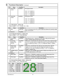
13.13 VID4 Register—Address 49h
<
>
< >
Power on default – 7:1 = 100 000, 0 = VID4.
Bit
Name
Read/Write
Description
0
VID4
Read Only
Bit 4 of VID data from the CPU or power supply that indicates the operating voltage
(e.g. 1.5 V to 2.9 V).
1-7 Reserved
Read/Write
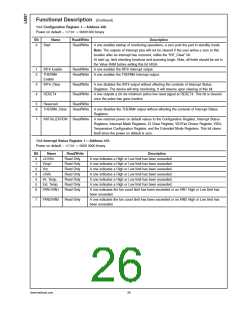
13.14 Configuration Register 2—Address 4Ah
<
>
Power on default – 7:0 = 0000 0000 binary
Bit
Name
Thermal INT#
Mask
Read/Write
Description
0
Read/Write
When this bit is set to 1, thermal error events will not affect the INT# interrupt
output. THERM# outputs will still function normally.
1
Local Temp.
Register Write
Once Bit
Read/Write
Once
When set to 1, this bit locks in the value set in the Internal Temp. high limit register
at 0x13h. The value cannot be changed until a power on reset is performed, or the
chip is re-Initialized by writing a 1 to Bit 7 of Configuration Register 1 (Register
40h).
2
Remote Temp.
Register Write
Once Bit
Read/Write
Once
When set to 1, this bit locks in the value set in the External Temp. high limit
register at 0x14h. The value cannot be changed until a power on reset is
performed, or the chip is re-Initialized by writing a 1 to Bit 7 of Configuration
Register 1 (Register 40h).
3
THERM# Interrupt
Mode
Read/Write
When set to 0, the THERM# output functions in Default mode. When set to 1, the
THERM# output functions in ACPI mode.
4-5 Reserved
IRQ3 Enable
6
Read/Write
Read/Write
When set to 1, VID3/IRQ3 is enabled as an active high interrupt input (if the
IRQEN bit is set in bit 7 of the Channel Mode Register).
7
IRQ4 Enable
When set to 1, VID4/IRQ4 is enabled as an active high interrupt input (if the
IRQEN bit is set in bit 7 of the Channel Mode Register).
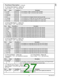
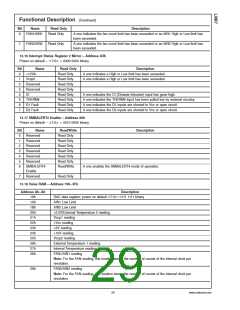
13.15 Interrupt Status Register 1 Mirror—Address 4Ch
<
>
Power on default – 7:0 = 0000 0000 binary
Bit
0
Name
+2.5Vin
Vccp1
Read Only
Read Only
Read Only
Read Only
Read Only
Read Only
Read Only
Description
A one indicates a High or Low limit has been exceeded.
A one indicates a High or Low limit has been exceeded.
A one indicates a High or Low limit has been exceeded.
A one indicates a High or Low limit has been exceeded.
A one indicates a High or Low limit has been exceeded.
A one indicates a High or Low limit has been exceeded.
1
2
Vcc
3
+5Vin
4
Int. Temp.
Ext. Temp.
5
www.national.com
28

 NSC [ National Semiconductor ]