Nexperia
PXP400-100QS
100 V, P-channel Trench MOSFET
9. Thermal characteristics
Table 6. Thermal characteristics
Symbol
Parameter
Conditions
Min
Typ
155
60
Max
195
75
Unit
K/W
K/W
K/W
Rth(j-a)
thermal resistance from in free air
junction to ambient
[1]
[2]
-
-
-
Rth(j-sp)
thermal resistance from
junction to solder point
10
12
[1] Device mounted on an FR4 PCB, single-sided copper, tin-plated and standard footprint.
[2] Device mounted on an FR4 PCB, single-sided copper, tin-plated and mounting pad for drain 6 cm2.
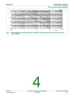
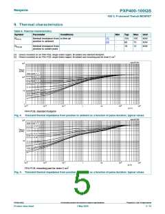
aaa-031141
3
10
Z
th(j-a)
(K/W)
duty cycle = 1
0.75
0.50
2
10
0.33
0.25
0.20
0.10
0.05
10
0.02
0.01
0
1
-3
10
-2
-1
2
3
10
10
1
10
10
10
t
p
(s)
FR4 PCB, standard footprint
Fig. 4. Transient thermal impedance from junction to ambient as a function of pulse duration; typical values
aaa-031142
2
10
duty cycle = 1
0.75
Z
th(j-a)
(K/W)
0.50
0.25
0.33
0.20
10
0.10
0.05
0.01
0.02
0
1
-3
10
-2
-1
2
3
10
10
1
10
10
10
t
p
(s)
FR4 PCB, mounting pad for drain 6 cm2
Fig. 5. Transient thermal impedance from junction to ambient as a function of pulse duration; typical values
©
PXP400-100QS
All information provided in this document is subject to legal disclaimers.
Nexperia B.V. 2020. All rights reserved
Product data sheet
7 May 2020
5 / 14

 NEXPERIA [ Nexperia ]