CHAPTER 3 SPECIFICATIONS OF PCI HOST BRIDGE MACRO
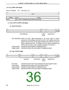
(2) How to access PCI configuration register
• Write access
Set the access target register address to the PCI_CONFIG_ADD register
↓
Write the access target register setting value to the PCI_CONFIG_DATA register
• Read access
Set the access target register address to the PCI_CONFIG_ADD register
↓
Read the PCI_CONFIG_DATA register
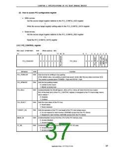
3.4.3 PCI_CONTROL register
After reset: 07000100H
31
R/W
24 23
Offset address: 08H
17 16 15
8
7
0
5
0
4
3
0
2
1
0
PCI_PARKCNT
0
0
0
0
0
0
0
PCI_REQ
Function
0
Bit Name
R/W
R/W Sets the time for shifting to bus parking.
PCI_PARKCNT
At the default value, bus parking is performed seven clocks after the bus status becomes IDLE.
The counter is started when FRAME# = High and IRDY# = High.
PCI_BPMODE
PCI_REQ
R/W Sets the bus parking master.
0: Limited to this macro
1: Master accessed last
R/W Enables/disables the REQ# signal (I_REQ_B1 to I_REQ_B7 pins) from the bus master.
Bit 0 of this field (bit 8 of the PCI_CONTROL register) is assigned to the PCI host bridge macro,
and is always 1.
0: Disabled
1: Enabled
PCI_RESET
TARGET_EN
MEM_EN
R/W Sets the reset status of the PCI bus.
0: Reset status
1: Reset released
R/W Sets the operation of the PCI bus target of the PCI host bridge macro.
0: Do not respond to main memory (SDRAM) access from the PCI device
1: Respond to main memory (SDRAM) access from the PCI device
R/W Enables/disables access from the CPU to the PCI memory area.
0: Access disabled
1: Access enabled
IO_EN
R/W Enables/disables access from the CPU to the PCI I/O area.
0: Access disabled
1: Access enabled
37
Application Note U17121EJ1V1AN

 NEC [ NEC ]