• This PDF catalog is downloaded from the website of Murata Manufacturing co., ltd. Therefore, it’s specifications are subject to change or our products in it may be discontinued without advance notice. Please check with our
• Please read rating and !CAUTION (for storage, operating, rating, soldering, mounting and handling) in this catalog to prevent smoking and/or burning, etc.
!Note
!Note
C02E.pdf
sales representatives or product engineers before ordering.
• This catalog has only typical specifications because there is no space for detailed specifications. Therefore, please approve our product specifications or transact the approval sheet for product specifications before ordering0. 9.9.18
• This PDF catalog has only typical specifications because there is no space for detailed specifications. Therefore, please approve our product specifications or transact the approval sheet for product specifications before ordering.
Notice
Continued from the preceding page.
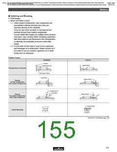
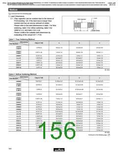
2. Land Dimensions
Land
2-1. Chip capacitor can be cracked due to the stress of
PCB bending / etc if the land area is larger than
needed and has an excess amount of solder.
Please refer to the land dimensions in table 1 for flow
soldering, table 2 for reflow soldering, table 3 for
GNM & LLA, and table 4 for LLM.
Chip Capacitor
c
Solder Resist
b
a
Please confirm the suitable land dimension by
evaluating of the actual SET / PCB.
Table 1 Flow Soldering Method
Dimensions
Chip (LgW)
a
b
c
Part Number
GRM18
1.6g0.8
GQM18
0.6 to 1.0
1.0 to 1.2
0.8 to 0.9
0.9 to 1.0
0.6 to 0.8
0.8 to 1.1
GRM21
2.0g1.25
GQM21
GRM31
LLL21
LLL31
ERB11
ERB21
ERF1D
3.2g1.6
1.25g2.0
1.6g3.2
1.25g1.0
2.0g1.25
1.4g1.4
2.2 to 2.6
0.4 to 0.7
0.6 to 1.0
0.4 to 0.6
1.0 to 1.2
0.5 to 0.8
1.0 to 1.1
0.5 to 0.7
0.8 to 0.9
0.6 to 0.8
0.9 to 1.0
0.8 to 0.9
1.0 to 1.4
1.4 to 1.8
2.6 to 2.8
0.8 to 1.0
0.8 to 1.0
1.0 to 1.2
8
(in mm)
Table 2 Reflow Soldering Method
Dimensions
Chip (LgW)
a
b
c
Part Number
0.4g0.2
0.6g0.3
0.16 to 0.2
0.2 to 0.3
0.12 to 0.18
0.2 to 0.35
0.2 to 0.23
0.2 to 0.4
GRM02
GRM03
GJM03
GRM15
GJM15
1.0g0.5
1.6g0.8
2.0g1.25
0.3 to 0.5
0.6 to 0.8
1.0 to 1.2
0.35 to 0.45
0.6 to 0.7
0.6 to 0.7
0.4 to 0.6
0.6 to 0.8
0.8 to 1.1
GRM18
GQM18
GRM21
GQM21
3.2g1.6
3.2g2.5
4.5g3.2
5.7g5.0
0.5g1.0
0.8g1.6
1.25g2.0
1.6g3.2
1.25g1.0
2.0g1.25
3.2g2.5
1.4g1.4
2.8g2.8
2.2 to 2.4
2.0 to 2.4
3.0 to 3.5
4.0 to 4.6
0.15 to 0.2
0.2 to 0.3
0.4 to 0.6
0.6 to 0.8
0.4 to 0.6
1.0 to 1.2
2.2 to 2.5
0.4 to 0.8
1.8 to 2.1
0.8 to 0.9
1.0 to 1.2
1.2 to 1.4
1.4 to 1.6
0.2 to 0.25
0.3 to 0.4
0.4 to 0.5
0.6 to 0.7
0.6 to 0.8
0.6 to 0.8
0.8 to 1.0
0.6 to 0.8
0.7 to 0.9
1.0 to 1.4
1.8 to 2.3
2.3 to 3.0
3.5 to 4.8
0.7 to 1.0
1.4 to 1.6
1.4 to 1.8
2.6 to 2.8
0.8 to 1.0
0.8 to 1.0
1.9 to 2.3
1.0 to 1.2
2.2 to 2.6
GRM31
GRM32
GRM43
GRM55
LLL15
LLL18
LLL21
LLL31
ERB11
ERB21
ERB32
ERF1D
ERF22
(in mm)
Continued on the following page.
154

 MURATA [ muRata ]