• This PDF catalog is downloaded from the website of Murata Manufacturing co., ltd. Therefore, it’s specifications are subject to change or our products in it may be discontinued without advance notice. Please check with our
• Please read rating and !CAUTION (for storage, operating, rating, soldering, mounting and handling) in this catalog to prevent smoking and/or burning, etc.
!Note
!Note
C02E.pdf
sales representatives or product engineers before ordering.
• This catalog has only typical specifications because there is no space for detailed specifications. Therefore, please approve our product specifications or transact the approval sheet for product specifications before ordering0. 9.9.18
• This PDF catalog has only typical specifications because there is no space for detailed specifications. Therefore, please approve our product specifications or transact the approval sheet for product specifications before ordering.
Notice
Notice
■ Soldering and Mounting
1. PCB Design
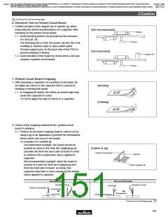
1. Notice for Pattern Forms
1-1. Unlike leaded components, chip components are
susceptible to flexing stresses since they are
mounted directly on the substrate.
They are also more sensitive to mechanical and
thermal stresses than leaded components.
Excess solder fillet height can multiply these stresses
and cause chip cracking. When designing substrates,
take land patterns and dimensions into consideration
to eliminate the possibility of excess solder fillet
height.
1-2. It is possible for the chip to crack by the expansion
and shrinkage of a metal board. Please contact us if
you want to use our ceramic capacitors on a metal
board such as Aluminum.
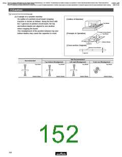
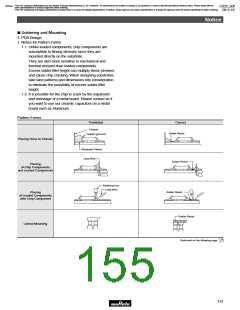
Pattern Forms
8
Prohibited
Correct
Chassis
Solder Resist
Solder (ground)
Placing Close to Chassis
Electrode Pattern
Lead Wire
Solder Resist
Placing
of Chip Components
and Leaded Components
Soldering Iron
Lead Wire
Solder Resist
Placing
of Leaded Components
after Chip Component
Solder Resist
Lateral Mounting
Continued on the following page.
153

 MURATA [ muRata ]