• This PDF catalog is downloaded from the website of Murata Manufacturing co., ltd. Therefore, it’s specifications are subject to change or our products in it may be discontinued without advance notice. Please check with our
• Please read rating and !CAUTION (for storage, operating, rating, soldering, mounting and handling) in this catalog to prevent smoking and/or burning, etc.
!Note
!Note
C02E.pdf
sales representatives or product engineers before ordering.
• This catalog has only typical specifications because there is no space for detailed specifications. Therefore, please approve our product specifications or transact the approval sheet for product specifications before ordering0. 9.9.18
• This PDF catalog has only typical specifications because there is no space for detailed specifications. Therefore, please approve our product specifications or transact the approval sheet for product specifications before ordering.
Notice
Notice
Continued from the preceding page.
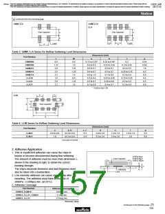
GNMpp2
GNMpp4
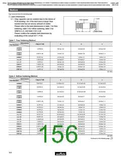
LLA
Chip Capacitor
Chip Capacitor
a
b
a
b
c
Land
Land
p
c
p
Table 3 GNM, LLA Series for Reflow Soldering Land Dimensions
Dimensions (mm)
Part Number
L
W
0.6
a
b
c
p
GNM0M2
GNM1M2
GNM212
GNM214
GNM314
LLA18
0.9
1.37
2.0
2.0
3.2
1.6
2.0
3.2
0.12 to 0.20*
0.4 to 0.5
0.6 to 0.7
0.6 to 0.7
0.8 to 1.0
0.3 to 0.4
0.5 to 0.7
0.7 to 0.9
0.35 to 0.40*
0.35 to 0.45
0.5 to 0.7
0.3
0.45
0.64
1.0
0.5
0.8
0.4
0.5
0.8
1.0
0.3 to 0.35
0.4 to 0.5
1.25
1.25
1.6
0.5 to 0.7
0.25 to 0.35
0.3 to 0.4
0.7 to 0.9
0.8
0.25 to 0.35
0.35 to 0.6
0.4 to 0.7
0.15 to 0.25
0.2 to 0.3
LLA21
1.25
1.6
8
LLA31
0.3 to 0.4
* 0.82Va+2bV1.00
p
c
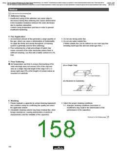
LLM
b
a
e
Chip Capacitor
c'
b'
f
d
Table 4 LLM Series for Reflow Soldering Land Dimensions
Dimensions (mm)
d
Part Number
a
b, b'
c, c'
0.3
e
f
p
LLM21
LLM31
0.6 to 0.8
1.0
(0.3 to 0.5)
2.0 to 2.6
3.2 to 3.6
1.3 to 1.8
1.6 to 2.0
1.4 to 1.6
2.6
0.5
0.8
(0.3 to 0.5)
0.4
b=(c-e)/2, b'=(d-f)/2
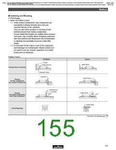
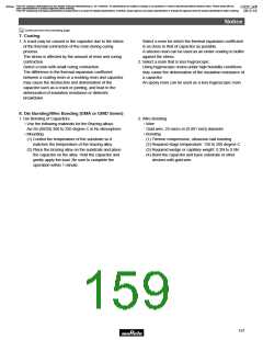
2. Adhesive Application
1. Thin or insufficient adhesive can cause the chips to
loosen or become disconnected during flow soldering.
The amount of adhesive must be more than dimension c,
shown in the drawing at right, to obtain the correct
bonding strength.
a=20 to 70µm
b=30 to 35µm
c=50 to 105µm
Chip Capacitor
a
c
The chip's electrode thickness and land thickness must
also be taken into consideration.
b
Adhesive
Land
Board
2. Low viscosity adhesive can cause chips to slip after
mounting. The adhesive must have a viscosity of
5000Pa • s (500ps) min. (at 25°C).
3. Adhesive Coverage
Part Number
Adhesive Coverage*
0.05mg min.
GRM18, GQM18
GRM21, LLL21, GQM21
GRM31, LLL31
0.1mg min.
0.15mg min.
*Nominal Value
Continued on the following page.
155

 MURATA [ muRata ]