Freescale Semiconductor, Inc.
Pulse Width Modulator
PWM Register Description
Bit 7
Bit 7
Bit 7
Bit 7
Bit 7
0
6
6
6
6
6
0
5
5
5
5
5
0
4
4
4
4
4
0
3
3
3
3
3
0
2
2
2
2
2
0
1
1
1
1
1
0
Bit 0
PWCNT0
PWCNT1
PWCNT2
PWCNT3
RESET:
Bit 0
Bit 0
Bit 0
Bit 0
0
$0048
$0049
$004A
$004B
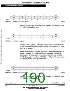
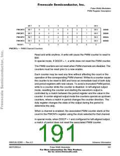
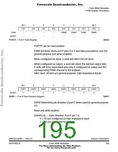
PWCNTx — PWM Channel Counters
Read and write anytime. A write will cause the PWM counter to reset to
$00.
In special mode, if DISCR = 1, a write does not reset the PWM counter.
The PWM counters are not reset when PWM channels are disabled. The
counters must be reset prior to a new enable.
Each counter may be read any time without affecting the count or the
operation of the corresponding PWM channel. Writes to a counter cause
the counter to be reset to $00 and force an immediate load of both duty
and period registers with new values. To avoid a truncated PWM period,
write to a counter while the counter is disabled. In left-aligned output
mode, resetting the counter and starting the waveform output is
controlled by a match between the period register and the value in the
counter. In center-aligned output mode the counters operate as up/down
counters, where a match in period changes the counter direction. The
duty register changes the state of the output during the period to
determine the duty.
When a channel is enabled, the associated PWM counter starts at the
count in the PWCNTx register using the clock selected for that channel.
In special mode, when DISCP = 1 and configured for left-aligned output,
a match of period does not reset the associated PWM counter.
68HC(9)12D60 — Rev 4.0
MOTOROLA
Advance Information
Pulse Width Modulator
191
For More Information On This Product,
Go to: www.freescale.com

 MOTOROLA [ MOTOROLA ]