MC33389
Freescale Semiconductor, Inc.
DEVICE DESCRIPTION
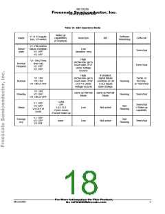
SBC MODES
Table 8. NormalRequest: V1 active, V2&V3 passive
Entering NormalRequest Leaving NormalRequest
When firstly receiving the
SBC reset just released
SW timing word, SBC
goes to Normal
SBC Sleep Mode
If time-out without receiving
SPI commands (75ms),
SBC goes to sleep
This is a low power consumption mode. V1 and V2 are
disabled. V3 can be permanently disabled or cyclically active.
Table 11. SBC Sleep Mode: V1 And V2 Are Passive, V3
Passive Or Cyclic.
SBC Normal Mode
In this mode, V1 and V2 are active, V3 can be set active or
passive via the SPI. Therefore, the whole ECU can be
operated. Normal mode is entered by a SWCR register
configuration in NormalRequest mode.
Entering Sleep Mode
Leaving Sleep Mode
If SW timing not configured
75ms after entering
CAN wake-up, going to
NormalRequest
NormalRequest mode
Table 9. SBC Normal Mode: V1 And V2 Are Active. V3 Is
Active Or Passive
If a wake-up is detected with
cyclic sense
By SPI command
Entering Normal Mode
Leaving Normal Mode
For MC33389ADW only: If
V1 is below V1 reset for
more than 100ms
If a wake-up is detected with
wake-up not connected to V3
(permanent sense)
By SPI command, going to
any other mode
By SPI command
Forced wake-up (See Forced
Wake up Section)
After SWCR register
configuration in
Watchdog time out, going
to NormalRequest after
activating Reset
NormalRequest mode
SPI wake-up (See Wake up
by SPI Section)
V1 undervoltage detection,
going to NormalRequest
mode after activating Reset
Emergency Mode
In case the microcontroller detects the ECU or the system
is not under control any more, it may decide to switch the SBC
to the Emergency mode. V1, V2, V3 will be passive and wake-
up are not detected. The only way to leave this mode is to
disconnect the ECU from the Battery voltage (BatFail
detection).
SBC Standby Mode
In this mode V1 is active, V2 is passive. V3 can be either
permanently active or permanently passive. This is a low
power mode with V1 active in order to have a fast reaction
time in case of any wake-up.
Table 12. SBC Emergency Mode: V1 And V2 V3 Are
Passive
For standby mode, the SBC monitors the SW. It means the
microcontroller runs and is monitored and must serve a
watchdog trigger.
Entering Emergency Mode Leaving Emergency Mode
SBC BatFail detection (Dis-
Table 10. Standby: V1 Active V2 Passive, V3 Active Or
Passive, Watchdog Is Active
By SPI command
connection of the Battery
voltage)
Entering Standby
Leaving Standby
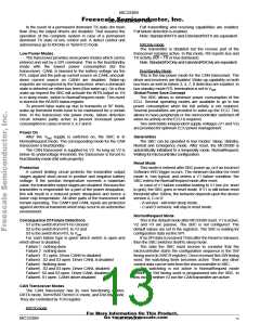
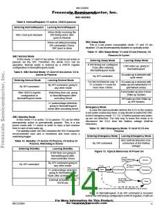
Figure 13. Typical Behaviour At Power On
If SW time-out going to
NormalRequest after
microcontroller Reset
SPI SW
timing configuration
Normal
at t<75ms
By SPI command going to
any other mode
By SPI command
SPI go to Emergency
at t<75ms
V1 low
Reset
V1 on
ECU
connected
to battery
NormalRequest
Emergency
Sleep
V1 undervoltage detection,
going to NormalRequest
mode after activating Reset
(reset
released)
No SPI SW
External activation of the
RSTB pin
timing configuration
at t=75ms
Vbat > 4V and V1 low for t>100ms for MC33389ADW only (A version)
Note: In Normalrequest, if an SPI command is received
before the SW timing configuration (SWCR register), it will not
For More Information On This Product,
Go to: www.freescale.com
MC33389
MOTOROLA
14

 MOTOROLA [ MOTOROLA ]