MC33389
Freescale Semiconductor, Inc.
DEVICE DESCRIPTION
Introduction
against short to ground (current limitation) and overtemperature.
The System Basis Chip is an integrated circuit dedicated
V2 is active in Normal mode.
to car body applications. It includes three main blocks :
- A dual voltage regulator
Undervoltage Detection
V2 is monitored for undervoltage and a flag is set in the
VSSR register.
- Reset, watchdog, wake up inputs, cyclic wake up
- CAN low speed fault tolerant physical interface
Overtemperature Protection
V2 internal ballast transistor is monitored for
overtemperature. Two detection thresholds are provided. A
pre-warning threshold at 140°C and a shut-off threshold at
165°C. Once the first threshold is reached, a flag is set in the
OTSR register which is readable. A maskable interrupt can be
sent to microcontroller.
Supplies
Two low drop regulators and one switch to Vbat are
provided to supply the ECU microcontroller or peripherals,
with independent control and monitoring through SPI.
Once the second threshold is reached, a flag is set in the
OTSR register, V2 is switched off. It can only be switched on
again via the SPI.
Voltage Regulator V1
V1 is a 5V, 3% low drop voltage regulator dedicated to the
microcontroller supply. It can deliver up to 100mA and is
totally protected against short to ground (current limitation)
and overtemperature. V1 is active in Normal request, Normal
and standby modes.
Table 5. V2 Control
Conditions For V2 On
Conditions For V2 Off
No forward parasitic diode exists from V1 to Vbat. This
Normal mode (via SPI) AND
Sleep mode, or standby
mode or NormalRequest or
emergency mode (via SPI)
means that, if Vbat voltage drops below V1, no high current
flowing from V1 to Vbat will discharge the capacitor connected
V2 below shut off
temperature threshold
to V1. Its stored energy will only be used to supply the
Shut-off temp.
microcontroller and gives time to save all relevant data.
threshold reached
V1 disabled
Undervoltage Reset
(for any reason)
V1 is monitored for undervoltage (power up, power down)
and a reset is provided at RSTB output for 1ms. This ensures
proper initialization of the microcontroller at power-on or after
supply is lost. On top of that, a flag is set in RSR register
readable via the SPI.
Switch V3
V3 is a 10Ω switch to Vbat, it can be used to supply
external contacts or relays. A great flexibility is given for the
different possible ways for its control. It is protected against
short to ground (current limitation).
Overtemperature Protection
Overtemperature Protection
V1 internal ballast transistor is monitored for
overtemperature. Two detection thresholds are provided. A
pre-warning threshold at 145°C and a shut-off threshold at
175°C. Once the first threshold is reached, a flag is set in the
OTSR register. A maskable interrupt can be sent to the
microcontroller. Once the second threshold is reached, a flag
is set in the OTSR register, a maskable interrupt is sent to the
microcontroller and V1 is switched off.
V3 output transistor is monitored for overtemperature.
Once the threshold is reached, a flag is set in the VSSR
register, V3 is switched off. It will be automatically switched on
once the junction temperature is back to the pre-warning
threshold.
Table 6. V3 Control
Conditions For V3 On
Conditions For V3 Off
Once the junction temperature is back to the pre-warning
threshold, V1 regulator it will be automatically switched on.
Permanently in Normal
Permanently in Normal
mode if configured via SPI
mode if configured
Permanently in Standby
NormalRequest mode
Table 4. V1 Control
mode if configured via SPI
In sleep mode, during
enable time of cyclic
sense if configured
Permanently in Standby
mode if configured
Conditions For V1 On
Conditions For V1 Off
NormalRequest mode
Sleep mode (via SPI)
(at V1 power on)
Permanently in sleep
mode if configured
In sleep mode, during
disable time of cyclic
sense if configured
Shut-off temperature
threshold reached
Normal mode (via SPI)
Standby mode
(via SPI)
No Vbat power supply
(cold start)
V1 below pre-warning
Emergency mode
Overtemp threshold reached
V1 disabled (for any reason)
V2 over temperature shutdown
temperature threshold
During Reset
Note: current capability of V1, V2 and V3 depends upon
the thermal management. Over temperature shutdown might
be reached and lead to turn off of V1, V2 and V3 for output
current below their max current capability.
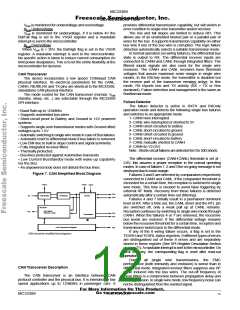
Supply and Vbat Block
Vbat Monitoring
Voltage Regulator V2
Vbat is the main power supply coming from the Battery
voltage after an external protection diode (for reverse battery).
V2 is a 5V low drop voltage regulator dedicated to
peripherals supply. It can deliver up to 200mA and is protected
For More Information On This Product,
Go to: www.freescale.com
MC33389
MOTOROLA
11

 MOTOROLA [ MOTOROLA ]