MC33389
Freescale Semiconductor, Inc.
DEVICE DESCRIPTION
WAKE-UP CAPABILITIES
Several wake up capabilities are available.
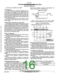
register. Once activated, V3 remains ‘on’ during 400µs. The
wake-up inputs states are sampled at 300µs.
Forced Wake-up
Figure 16. V3 Timing
The forced wake-up is enabled and disabled by SPI in
V3R register. It is used in sleep mode to automatically wake-
up the system by supplying V1 with proper reset. This
correspond to jump into NormalRequest mode. If then, the
SBC is not properly configured within 75ms, it switches back
to sleep mode till the next wake-up. If both Cyclic sense and
forced wake-up are enabled by the SPI in sleep mode, only
Cyclic sense will be active.
wake-up inputs sample point
active
V3
passive
300us
400us
cyclic sense programmable period
The period of forced wake-up are 32ms, 64ms, 128ms,
256ms, 512ms, 1024ms, 2048ms, 8192ms, chosen by SPI in
CYTCR register.
Note: In sleep mode, the Cyclic Sense feature
‘EXCLUSIVE OR’ the forced Wake-up is chosen (not both).
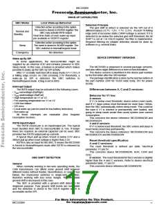
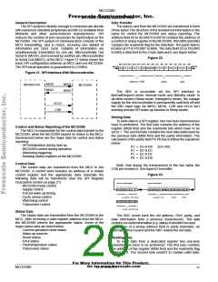
Wake-up Inputs (Local Wake-up) / Cyclic Sense
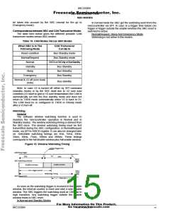
Figure 17. Cyclic Sense Timing
SBC provides 3 wake-up inputs to monitor external events
such as closing/opening of switches. The wake-up feature is
available in Normal, Standby and sleep modes. The switches
can be directly connected to Vbat or to V3. The SBC must be
properly configured by setting bit WI2V3 in register V3R. In
this case, wake-ups are only detected when V3 is On. It can
take advantage of V3 cyclic sense feature. If both Cyclic
sense and forced wake-up are enabled by the SPI in sleep
mode, only Cyclic sense will be active.
Cyclic sense connected to wake-up inputs. Example with wake-up input L1
sensitivity to Low state and timing=80ms
V3
wake-up
OPEN
CLOSED
switch status
sample point (80%)
setup
V(L1)
Read L1
INTB
Options For Wake Input
300µs
Different conditions for wake-up can be chosen for wake-
up input pins (via SPI in WUICR register).
read
400
µ
s
No wake-up: No wake-up is detected, whatever occurs on
wake-up inputs.
0
80ms
(t1)
160ms
(t0)
High state: if the input pin voltage is above the detection
threshold during more than a 20µs filter time, a wake-up is
detected. A flag is set in the WUISR register.
Low state: if the input pin voltage is below the detection
threshold during more than a 20µs filter time, a wake-up is
detected. A flag is set in the WUISR register.
Change of state: each change of the wake-up input pin is
considered as a wake-up, if it lasts more than a 20µs filter
time. The first reference state (no wake-up) is the wake-up
input state when the SBC is programmed to this option. A flag
is set in the WUISR register.
1
1
1
0
1
1
0
0
0
actual state (read)
memory state
INTB (wake-up active=0)
Wake Up Inputs With Permanent Sense
Wake up detection can also be done on a permanent way
in Normal and Standby mode. If the contacts are connected to
V3, wake ups are only detected if V3 is on.
Wake ups are also detected on a permanent way in sleep
mode if the contacts are directly connected to Vbat (if they are
connected to V3, only cyclic sense is available in sleep mode).
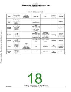
Multiple sampling events: when wake-up inputs are used
with V3 in cyclic sense in sleep mode.
Local Wake-up Consequences
For positive edge sensitivity, 2 samples Low followed by 2
samples High are necessary to validate the wake-up
condition.
In normal or standby modes, the real time state of each
wake-up input pin is stored in the readable register WUIRTI.
Wake-ups are detected according to the option chosen. A flag
is set in the WUISR register. A maskable interrupt is sent via
INTB output.
For negative edge sensitivity, 2 samples High followed by
2 samples Low are necessary to validate the wake-up
condition.
In sleep mode, a local wake-up leads to a jump to
NormalRequest mode (via proper reset of the microcontroller). A
flag is set in the WUISR register.
For both edge sensitivity, 2 samples at a given state
followed by 2 samples in the opposite state are necessary to
validate the wake-up condition.
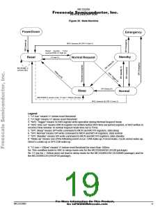
Table 18. SBC Mode Versus Local Wake-up Behaviour
Wake-up Inputs With Cyclic Sense
Connecting the external switches to V3 allows power
saving since V3 can be programmed to be active, passive or
cyclic (cyclic sense). This gives a great flexibility to reduce
total power consumption while allowing full wake-up
capabilities. Cyclic sense is available only in sleep mode.
The period of the Cyclic sense can be chosen out of 8
different timings: 32ms, 64ms, 128ms, 256ms, 512ms,
1024ms, 2048ms, 8192ms programmable via SPI in CYTCR
SBC Modes
Local Wake-up Behaviour
NormalRequest
No detection
For More Information On This Product,
Go to: www.freescale.com
MC33389
MOTOROLA
16

 MOTOROLA [ MOTOROLA ]