MC33389
Freescale Semiconductor, Inc.
DEVICE DESCRIPTION
Thermal Management
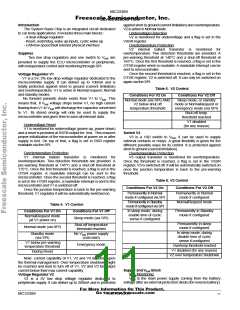
SO28WB Package
The MC33389 is proposed in two different packages.
HSOP20 for high power applications and SO28WB with 8 pins
to the leadframe for medium power applications.
The case(pin) to junction Rth is here represented by only
one thermal resistance for the total power since the 3 power
sources strongly interact on the silicon for such a package.
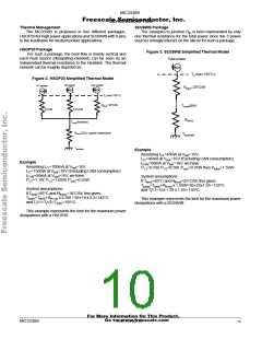
HSOP20 Package
Figure 3. SO28WB Simplified Thermal Model
For such a package, the heat flow is mainly vertical and
each heat source (dissipating element) can be seen as an
independent thermal resistance to the Heatsink. The thermal
network can be roughly depicted as:
Total power
Tj (max 155°C)
Rthj/c=20°C/W
Figure 2. HSOP20 Simplified Thermal Model
V2 power
Can power
V1 power
Tj (max 155°C)
Rthj/c=18°C/W
Tcase(pin)
9°C/W
6.5°C/W
Rthc/a
Tcase(heatsink)
Rthc/a (ECU supplier dependent)
Tambient
Tambient
Example
Assuming IV1=45mA at Vbat=16V,
IV2=45mA at Vbat=16V (Excluding CAN consumption).
ICAN=50mA at Vbat=16V, we have :
PV1=0.5W, PV2=0.5W, Pcan=0.55W thus Ptotal=1.55W
Example
Assuming IV1=100mA at Vbat=16V,
IV2=150mA at Vbat=16V (Excluding CAN consumption).
ICAN=50mA at Vbat=16V, we have :
System assumptions:
PV1=1.1W, PV2=1.65W, Pcan=0.55W
If Tamb=85°C and Rthc/a=25°C/W, this gives:
Tcase=Tamb+Rthc/a x 1.55W=85+25x1.55 =124°C
and TjV1=124 + 20 x 1.55= 155°C.
System assumptions:
If Tamb=85°C and Rthc/a=18°C/W, this gives:
Tcase=Tamb+Rth c/a x 3.3W = 85+18 x 3.3=145°C
and TjV1=TjV2=Tjcan=155°C.
This example represents the limit for the maximum power
dissipations with a SO28WB.
This example represents the limit for the maximum power
dissipations with a HSOP20.
For More Information On This Product,
Go to: www.freescale.com
MC33389
MOTOROLA
10

 MOTOROLA [ MOTOROLA ]